
Some little time ago I purchased a "Spares or Repair" Trio-badged TS-180S from an eBay Trader, the price I paid reflected its non-working condition. I didn't know very much at all about the TS-180S at the time but fancied a challenge.
As I've put my Eden9 70MHz transceiver on the "back burner" for a while and cleared one or two other repair jobs, I finally decided that the time was right to make a start on the '180S.
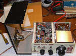
A preliminary look under the lid on the day the radio arrived revealed that the radio was totally u/s. The famous Trio/Kenwood "dots" on the display on all bands, and a quick poke around with a DVM revealed that the regulated outputs from the "AVR" board were all over the place. The whole thing smacked of multiple problems so I was anticipating a bit of a struggle. The radio may yet prove to be Beyond Economic Repair, only time can tell if that is going to be the case.
Forearmed with this knowledge I decided to have a look at the AVR board for starters.
This consists of three regulator circuits. One is a DC-DC converter which produces a light duty negative rail. This appears to be working fine.
The other two parts are shunt regulators (oh dear, I dislike shunt regulators!) producing 8 volts (adjustable) and 8.1V (non-adjustable) respectively. These were producing 5 and a bit volts which didn't respond to adjusting and 8.9 volts respectively but are independent of one another save for the fact that the unregulated input rail is common to both.
As it seemed to be the most out of kilter I decided to look at the 8V adjustable supply first.
Having scribbled the circuit out on a pad and made some voltage measurements and jotted them down I homed in on what I felt would be a likely candidate for being faulty. Shunt regulators are pretty horrible circuits in my view, not so much due to their complexity (they aren't usually all that complex) but due to the way the various stages (voltage reference, error amplifier, regulator driver and regulator) are wrapped up in a tight loop and DC-coupled, fault finding on them can be tricky as a fault in one part of the circuit ripples right through the circuit cutting off or destroying transistors and causing Magic Smoke to be lost from the system.
I didn't appear to have any overstressed components in my circuit, but I certainly appeared to have transistors which were just acting like resistors so I took a punt on the regulator driver being a suspect worthy of investigation. What I found amazed me.
I removed (or so I thought) some solder from the PCB pads under Q5 the suspect device and tugged on it from the top, and away it came fairly easily. However I noticed that the transistor legs seemed to be somewhat corroded, surprisingly, and I cleaned them off a bit with my pliers and tested the transistor on my DVM. It looked absolutely fine.
Well I wasn't 100% convinced that Q5 was the culprit, and with it removed from the circuit, it would make the results of some other resistance tests on the remainder of the circuit easier to interpret, so I wasn't too discouraged. However, when my attention returned to the board I noticed that I had actually de-soldered the wrong components, probably due to my not having been able to find my near-distance glasses! The corroded remains of the transistor legs were still firmly attached to the PCB.
I managed to find a similar transistor to the original Japanese one in my junk box and eventually after some mental gymnastics with the different pinout replaced the original unit and re-soldered the remaining components.
The 8V regulator now works and is adjustable, so the original transistor must have had such badly corroded legs that it must have just basically appeared as a resistor network to the circuit. I've never come across anything quite like that before in my fault-repairing experience.
Even better news, with the 8V supply restored, the radio is now showing some signs of life. The PLL appears to lock on some bands (10,14 and 21MHz, though not across the whole band.
Nothing is being received even with the PLL locked, but it is a start!
I still have to figure out where the corrosion which ate the legs of the transistor came from - perhaps something liquid was dropped through the grille of the external case (this board is directly under the vent grille as it generates a reasonable amount of heat)?
Rallies
4 hours ago

Good show Martin, glad you have made a start and the thing that i would do now is to look at what is below that board as if there was spillage and it seems that there had been, then look below it to see how far it went down.
ReplyDeleteIt never amazed me how far it went and what weird faults it gave but what a great feeling when it finally worked as i am sure it will do.
73 Ken
'what was the proble form dots counter display? i have paid 20dollars to adquiere them, but have the dots display problem and has ugly touched...
ReplyDeleteCiao, I'm sorry if I'm disturbing you, I'm repairing this ts180.
ReplyDeleteProblem 1
On the avr board adu 8th is ok, 8.1 on to under load is showing 9.2 but to is in parallel with q8 which should be at 9.2v the radio powers up but on the display only dots.
Start investigating on premix unit (peoblem2)
No signal input on premix but all dc voltages seems ok!
On TPl i have 46.6 KHZ, CAR is stable at 8.0MHZ
On TP5 no signal!
No CTR SIGNAL to the display eat her. I don't know where to start,
Can you point me in the right direction?
Thank you very much