Showing posts with label electronics. Show all posts

Sunday, 13 April 2014

Don't Turn it On, Take it Apart (a homage to EEVBlog)

Don’t Turn it On, Take it Apart!

So says Dave L Jones, the man behind what I think is the best channel on YouTube, EEVBlog.

If you haven’t paid EEVBlog (which stands for Electronic Engineering Video Blog) a visit yet, you simply MUST.

Dave is (inter alia) an experienced electronic design engineer turned full time Video blogger who happens to live in Sydney, New South Wales Australia.  

 He’s passionate, entertaining articulate, knowledgeable and opinionated, and above all as “Australian” as they come, and rightly proud of it.

His video blogs cover a wide range of subjects including equipment reviews (Dave seems to have a Test Gear fetish!) “teardowns”, tutorials and rants.

His approach might be regarded as rather brash by some, and his language occasionally becomes slightly “colourful”, but I find his no-nonsense-tell-it-like-he-sees-it approach extremely refreshing, and not agreeing one hundred per cent with everything he says is just part of the appeal.

Introducing a “Fair Dinkum Flying Pig”

As an appetiser may I suggest the following viewing for your maximum entertainment?

EEVBlog #39 – Microchip PICKit 3 Programmer Review

Microchip Response to PICKit 3 Review from EEVBlog #39

EEVBlog #41 – Pigs fly at Microchip

Dave admits in his 500th episode – a 5 hour “live” show, when asked by one of his online chatroom colleagues that this series are amongst his own particular favourites of all the shows he has done.

As the man says : “check it out”!


Wednesday, 28 March 2012

Electronic Experimentation (Spiralling Off . . .)

I wish now to relate something of the pleasure which can be experienced whilst carrying out simple experiments.

The Nutty Professor is at it again ! ! !


As many who experiment with home construction would no doubt relate, one thing quite often leads to another, which in turn leads to another, and so on (or to misquote a line from the "Commitments" movie - they go "spiralling off").

It's a wonderful thing on the whole, but one of the frustrations with it is that one never seems to get anything quite finished!

Readers of earlier blog entries will have spotted references to crystal controlled transmitters and receivers for use with the QRSS aspect of the amateur radio hobby.

Successful (one hesitates to say "the best" as this implies some sort of competition, and I don't think QRSS folk are particularly competitive) QRSS stations, whether simple or complex have to be well engineered.

Sloppy engineering practice soon becomes evident, manifesting itself in unreliability or in poor performance, and the poor performance I am thinking of in particular is that of frequency stability, or rather the lack of it.

My own home made efforts have exhibited acceptable, if not outstanding stability, and one quickly looks to ways of improving performance.

For some time now I have been pondering this issue, and a chance visit to a rather interesting web site produced a nicely written article explaining how to make a simple crystal heater
.
Thermostatic control of the temperature of the crystal used to produce the QRSS signal, or local oscillator in the case of a receiver seems to be a fairly obvious thing to do, and I had already looked at a commercial offering which offers high stability for a few pounds, and is a microcontroller based solution.

The heater to which I am referring though is a much simpler affair using a darlington transistor to modulate the flow of current through some low value resistors (the heating elements), with a thermistor to provide regulation and feedback.

This struck me as a brilliantly simple idea, so I resolved to build something similar if not quite identical.

With the exception of the thermistor, all parts came out of my junk box, in fact the darlington transistor was concocted from a small power transistor rescued from some long-forgotten project (the leads had been cut and had traces of old solder on them) and a low power Japanese 2SC something-or-other freshly removed from a scrap board which was probably a transistor radio or portable TV 20-odd years ago. Total cost of parts, probably quite a bit less than a pound.

The crystal being thermally controlled (heated) is physically but not electrically connected to a heated piece of thin tinplate (formerly part of a screening can also rescued from a scrap board).

When connected up to a power supply, my little heater worked first time (it is so simple it could hardly fail), and after some experimentation with the settings I had it heated up to just under 40 deg C, and was able to adjust the crystal FREQUENCY (the crystal was electrically connected to a completely separate test oscillator) by tweaking the temperature of the heater. The heater once it reached equilibrium maintained its set temperature perfectly.


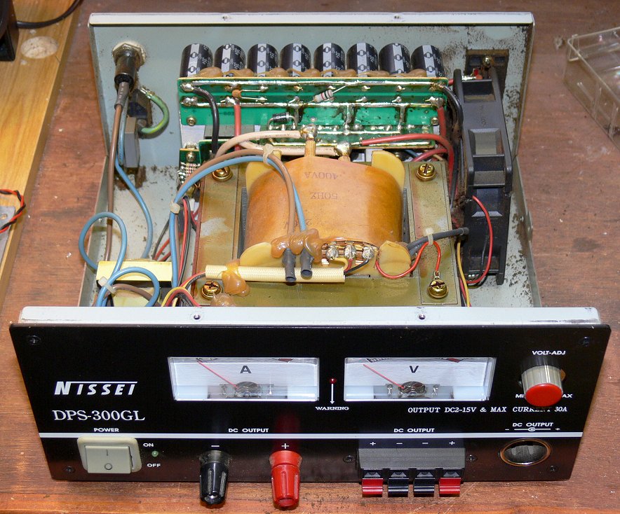
My test set up involved monitoring the current drawn by the circuit, and the collector voltage of the transistor.

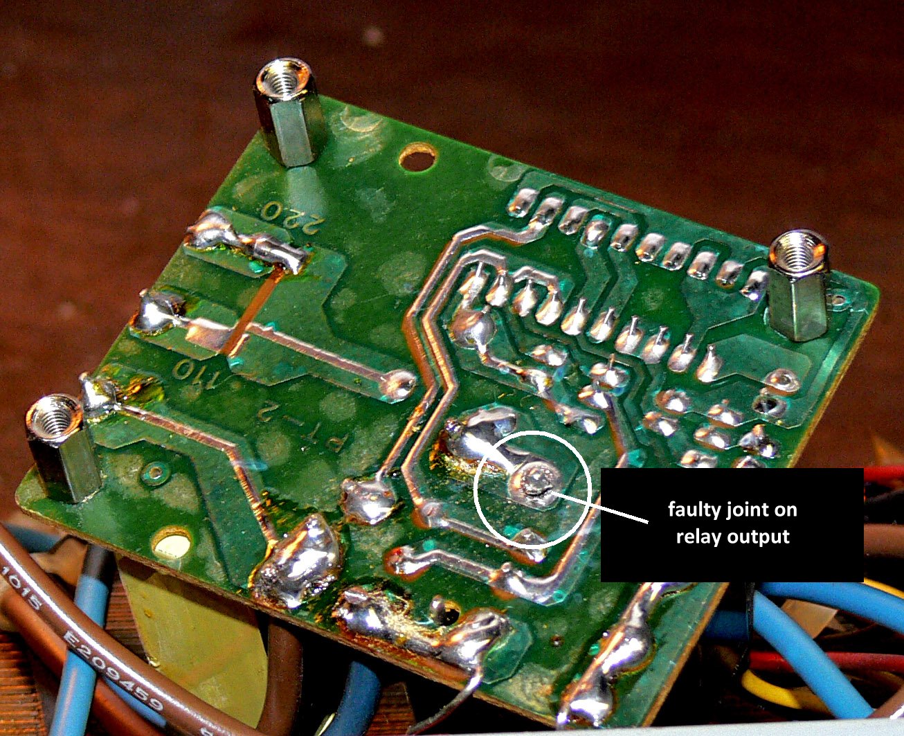
Pretty it ain't - interesting it certainly is!
Inspection of the circuit shows that they go in opposite directions - when the collector is high, the current drawn (and therefore the power being dissipated in the heater resistors) is low, and vice versa. If the surroundings change, or the circuit is heated up or cooled down deliberately the circuitry compensates for the changes very quickly thus restoring equilibrium.

One quickly realises that this little heater is really trying in its own small way to regulate the temperature of the
whole planet, and for it to be as economical as possible, it needs to be thermally insulated as much as possible from the outside world, and a little more thought reveals that in a way this little circuit is a miniature representation of, say, a domestic dwelling where the occupants try to maintain a comfortable temperature inside when the weather may be up to all sorts of tricks on the outside.
The heater schematic


Fascinating.

Also, as I have an interest in the application of microcontrollers, this application is also, as stated above, one where a microcontroller could be used, but this is where one needs to think about cost. Even buying new components, the unit cost of my little device would be no more than a pound, and the cheapest microcontrollers cost in the region of 75 pence per unit, so by the time you've bolted any additional components required, the simple version probably wins out, but only just. Die hard microcontroller enthusiasts would probably dispute that assertion!
Either way the mere consideration of one approach versus the other illustrates perfectly how experimentation can lead one through all sorts of interesting thought processes, which is really the whole point of me writing this note.

Saturday, 25 February 2012

The Mad Mad World of Microcontrollers

It's been a while since my last blog, and that has been bugging me to the point where I feel I have to "tick the box" and "blog SOMETHING", so here it is.

The last entry was made shortly after I'd "discovered" the Arduino system, and this discovery has let me spiralling off into all sorts of strange directions, all associated with microcontrollers, one way or another.

In the meantime I've bought what I think is a rather good book called "The Quintessential PIC Microcontroller" by Sid Katzen which deals with the subject manner in a way which resonates with the way I approach things.   Recommending books is a dangerous business, rather like recommending restaurants or wines or other things which are extremely subjective in nature, so all I will say is that I think it's rather good and leave it at that.

I've also acquired a few bits and bobs associated with Atmel AVR microcontrollers (an Atmel AVR is at the heart of the Arduino), namely a "TinyUSB" programmer, a few low-end microcontrollers, an LCD panel, and I've just downloaded the AVR Studio IDE package from the Atmel web site.

Buying expensive text books apart (I only have a couple of microcontroller books, honestly!) the best way to "learn microcontroller" is by doing stuff, so that has now become the prime objective.

I should relate the story where my eyes were opened about the desirability of using microcontrollers.  This was when I was participating in a Radio Club project to scratchbuild a 70MHz transceiver (The Eden 9 Project) and had got to the point where working IF strips were emerging from our group of constructors.

The IF strip had been deliberately designed without an AGC system, but with the facility to add AGC later, and a prototype audio-derived AGC system was duly demonstrate.

Now some people are rather "sniffy" about audio-derived AGC - I may or may not have been one such sceptic, I couldn't possibly comment! - but this demonstration was remarkable!   Not only was the performance of the circuit so impressive, but the parts count (and cost) was so low!  

Of course, as I am sure you have worked out already, there was a PIC microcontroller at the heart of this little add-on board, and when one stops to consider how the "all analogue" alternative might have been designed then it doesn't take long to realise that the alternative would be more complex, costly and less flexible.   With a microcontroller prototype, just changing a few numbers inside the embedded program is the way performance is tweaked.  To cap it all the PIC at the heart of this unit retails at around a pound at time. Good value, or what?

All I need now is the time, willpower and inspiration to get down and learn the ropes properly.

Sunday, 31 July 2011

Voltage Probe Antenna - Part 2

This weekend saw a family visit (wife, grown-up children, and in-laws) trekking across the Pennines to the Sunderland Air Show, and a Jolly Good Day Out was had by all.
As with the Windermere Air Show we attended a couple of years ago, the only flying Avro Vulcan XH558 once again stole the show.  What a stunning aircraft, and what an impressive noise!

A fly-past with the bomb bay open

Today, in between watching the Hungarian Grand Prix and listening to the Second Test against India at Trent Bridge, I managed to get the prototype Voltage Probe Antenna completed and fired up for a quick test.

It certainly works, and in the brief period of time I had to test it before I packed up for the weekend, I had received amateur signals at good strength on all bands from 160m to 15m ,with the exception of 60m.

First VPA lash-up
I also had broadcast signals on Long Wave and Medium Wave at decent strength.  Next week I hope to carry out a more extensive evaluation, and naturally I will probably report back here.

This first version doesn't have the required circuitry to be powered from the output coax cable, this will follow in due course, no doubt.

Thursday, 3 March 2011

Thank Goodness for Electrolytic Capacitors (they keep lots of folk in work!)

I'm on a bit of a roll as far as fixing stuff goes.

 
The latest bit of gear to succumb to my endeavours is an old D-Link DE-812TP Ethernet hub rescued from the scap pile at work and which had failed in industrial use. It was being discarded as being "beyond economic repair".  Had the unit been somewhat more youthful it may well have gone back to the company's repair shop but as it dated from 1997 it was regarded as "consumable" and should have been destined for recycling.  In a previous life (or so it seems) it could well have been down to me to repair the hub myself!


Seeing an opportunity to acquire a potentially useful piece of equipment at no cost, and, frankly, fancying the challange,  I opted to have a quick look at it, as having seen the fault symptoms I thought there was a reasonable chance of making a repair.


The fault symptoms were rapidly flashing LED indicators (ALL of them were flashing) which strongly suggested a power supply fault.   There appeared to be no blown fuses either, a good sign.


Opening up the unit I discovered a small switched-mode power supply on a separate sub-board bearing a strong resemblance to a standard computer type supply, albeit a miniature version, without cooling fans and the like.   The general arrangement looked very familiar so confidence was high.


The first step was to prove that the main motherboard was OK, so I disconnected the built-in supply and provided a temporary 5V feed to the motherboard which immediately sprang into life with "normal" indications on the LEDs.   I was now more confident than ever that the PSU was the culprit so out it came for a closer examination.


Not having the circuit I had to make rough guesses about where and what the various circuit sections were, but I quickly identified what was probably the main capacitor filter section for the +5V supply and decided to test the reservoir capacitors with my Peak Electronics ESR60 Capacitor Analyser.   Years of experience of repairing electronic circuits teaches one to suspect electrolytic capacitors before anything else!   Strange readings were obtained with the capacitors in circuit (this is often due to other components connected to and across the capacitors and doesn't necessarily mean that there is a problem), so I unsoldered and removed them from the PCB in order to check them out of circuit.


See the photo below.


Once capacitor came out minus one of its legs (not a good sign!) and the other measured "Low Capacitance" on the meter.  They were both branded as 1000uF 16V units.    There was possibly some evidence on the PCB in the form of a small light brown stain resembling a drop of dried out spilt coffee that there may have been some electrolyte leakage, but it was clear that both of these capacitors were u/s.   As you can see from the photo they were also branded as 105 deg C capacitors so it would have been reasonable to expect a long life from them.    Still the hub had been in service 24/7 for around 12 years which I suppose is reasonable.  Around 100,000 hours of  continuous operation before failing.   As the two capacitors are connected in parallel in this circuit one can ponder that perhaps they had been dying gracefully for some considerable time, but one never knows.


Happily, the capacitors were replaced with new units purchased cheaply on EBay, and the PSU and its parent hub are now back up and running, seemingly as good as new.

Saturday, 19 February 2011

A "Doing" Day (in the shed)

A few days ago a Skype message from one of my small group of "Skypees" alerted me to the fact that an equipment failure had occurred. Jim's 30 amp power supply was no more. I was being asked what I thought about a couple of possible replacements, but as I enjoy the challenge of "fixing things", and also generally far too parsimonious to countenance replacing something old with something new without at least putting up a fight, the Skype conversation quickly got round to the faulty equipment and to what might be wrong with it.

With almost astonishing speed I was appraised of fault symptoms and then a copy of the circuit diagram. It was completely dead. Nothing coming out of it, apparently. Nil. Zip. Nada. Not even "magic smoke".

The circuit diagram was examined and I figured out some likely causes, all which seemed to be fairly straightforward to resolve, and so it was arranged that I would call in to see my friend when I was passing his home a few days later.

In the meantime, my friend proceeded to purchase a replacement unit (a hundred pounds, near as dammit!) and was very pleased with it.

The broken power supply was duly collected yesterday afternoon, and today I decided to take a look at it.

The power supply is called a "Nissei DPS-300GL" and is quite a hefty beast. Opening it up I found it to be quite nicely constructed, albeit rather grubby as the cooling fan had been dragging unfiltered air in and across the internal heatsink for many an hour. However, no matter what the outcome of my efforts was, the fan would drag no more air as it was completely seized up beyond redemption.


Inside the Nissei PSU (quite neat isn't it?)


My earlier deliberations had led me to suspect a problem with the overvoltage circuit, but I adopted a technique I have used on many occasions to prove or otherwise the general health of power supplies, and that was to connect a current limited supply at the correct DC voltage across the main rectifier output. Encouragingly this brought the majority of the power supply to life, at the same time lending weight to my original theory about the overvoltage tripping circuit which was fed from a completely separate supply via its own transformer.

Next I moved the external supply to the rectifier in the overvoltage circuit, and to my slight surprise the "enabling" relay (the overvoltage trip drops out the relay which removes the AC mains supply to the main power supply transformer) was heard to operate. My original theory was that there was a fault with this relay, or its associated driving circuitry.

Fortunately this piece of circuitry is built on its own separate board and was relatively easy to extract and examine.

It didn't take long with an eye-glass and a multimeter to get to the root cause of the problem - see the attached photograph.
Underneath the Overvoltage Board ...

A nasty looking joint at the relay contact which switches the AC mains to the main part of the power supply. Bingo!

The joint was cleaned up and resoldered, the overvoltage circuit returned to its rightful place, the PSU powered up from its own mains supply, and lo and behold the PSU is now working, albeit temporarily without a cooling fan.   I realised at this point that the description of the original fault symptoms must have been slightly wrong in that the trip relay would have been heard to operate upon the application of mains, and I didn't verify this myself. Having said that this might have made me more worried about what the cause of the fault was!

Having spent a few frustrating minutes wrestling with Maplin's web site looking for a replacement,  EBay was consulted, and a 92mm 12V DC fan was quickly found and has been ordered for the princely sum of £4.99 (including postage!).

Soon Jim will have a spare power supply.

Right!  On with the next job ...

Today is the day I finally decided to start building my "X-lock", a VFO stabiliser kit from local firm Cumbria Designs.   I've had this "in stash" for quite a while as other projects have got in the way.  Once built I have then to decide which rig of my various"old ladies" will get the benefit.  At the time of writing I think it will be my FT-107, but that is by no means certain.   I also have it in the back of my mind to build the version described by Eamon Skelton EI9GQ which seems to be a variation upon the same theme.   Still, that will be a way off as I still have to "cut my teeth" properly with PIC programming, another medium-term objective of mine.  It will be interesting comparing the performance of the two units, and the advantage of the EI9GQ version is that the PIC source code is in the public domain, and I would have the opportunity to experiment with it.
X-Lock construction under way

Anyhow construction of the X-lock has now commenced, hopefully it can be finished off tomorrow, with luck.