Sunday 11 December 2011

RC-14 - An Old Project Revisited

Way back in June 1987, the RSGB published an article in RadCom describing the "RC-14", a relatively simple "beginners" single band (20m) direct conversion receiver.    This was "kitted" by the then popular "Cirkit" emporium, and was offered at an attractive price to RSGB members.

This was, in my view a very well designed piece of equipment, and contained only three integrated circuits (one of the famous and rather splendid Plessey "SL" ICs and a couple of op amps configured as active filters with characteristics very similar to those of a high-performance crystal SSB filter) plus a varactor-tuned VFO, and the end result was a very pleasing receiver.

I built the receiver not long after it was published using the approved kit, and adapted it to my "bespoke" requirements - I disliked the flimsy enclosure provided and moved it to a more mechanically sound but less aesthetically pleasing aluminium die-cast box, and replaced the linear slider tuning pot (remember it was a varactor based design) with a rotary multiturn unit, albeit at great expense, and used it for a while (as you do) and moved on . . .


My version of the RSGB RC-14

Recently, I have become interested in the "QRSS" aspect of the hobby which is based around the transmission of very low power, low signalling rate beacon signals for extended periods which are received at various locations around the globe using PC-based "grabber" software.

Participation in this requires either the setting up of a "grabber" receiving station, or the use of a low power "MEPT" (Manned Experimental Propagation Transmitter), or in some cases both, though not necessarily at the same time!

Over the last few weeks I have been doing either and even occasionally both (!) using conventional equipment, and by "conventional" I mean "High Performance Japanese Transceivers", certainly as the receiving station, but it occurred to me recently that it was possible overkill using such high-spec equipment to perform such relatively mundane tasks.   In a flash of inspiration (or something!) I remembered my RC-14, and began to wonder if that could be dragooned into service as a QRSS receiver.

The built-in VFO, though adequate for general receiving purposes was certainly not of the required specification as a QRSS receiver, where frequency stability is a primary requirement, but the substitution of the built-in VFO with a crystal-based, or even synthesiser-based local oscillator would seem to be a Good Idea.

If you are following the argument, then by now you will surely have picked up on the mental thread . . .

And so, another project is born!

Sunday 27 November 2011

TS-180S - this is getting ridiculous!

I knew it was a mistake putting the lid on properly.
Having restored the functionality of the frequency display I decided to run the radio for a few hours over the weekend to evaluate performance further.   Still no tx, of course or any PLL locking on 28MHz but I knew that already ...
I was listening to a QSO on 7MHz this morning between a very strong Belgian station and a string of UK stations, most of whom I could hear reasonably well when I realised that the frequency seemed to be locked on to 7.150.0MHz.  Tuning either side by a kHz or two made no difference to the display.   I had a funny feeling about this, so I tuned up and down the band to find that lo and behold that the display was only displaying frequency to a 10kHz resolution!
To see whether this was a heat related issue I switched the radio off and let it cool down for half an hour or so, but on re-powering the fault was still present, so I have concluded that I have ANOTHER dead chip!  More than likely a duff 7490 in the counter chain, and that's TTL not CMOS, so another theory goes down the pan.
It is now only sheer stubbornness which is sustaining my interest in this project.  In all the years of building and repairing equipment, I don't think I've ever come across a project like this.   Trying to fix up a radio with numerous faults is one thing (and what I thought I was dealing with here), but fixing one which keeps breaking seemingly randomly whilst under repair is quite something else.   It's a case of either "nolum illigitimus carborundum", or chuck the bloody thing in the (recycling) bin!  I don't give up easily though.  What kind of trauma has this radio suffered in the past?   It's anybody's guess.

Saturday 26 November 2011

TS-180S Display Fixed (Again!)

As I reported previously I discovered that the display in my TS-180S which is currently undergoing major restoration was again faulty.

The symptoms were either that it displayed just the "base" frequency of the band in use when it was powered up, "1.500.0" for example on Top Band, "3.500.0" on 80m, or another sequence of numbers unrelated to anything.  None of these numbers changed when the bandswitch was operated with the set switched on.

A couple of nights ago I decided to have a look with my test gear to find out what was going on, or not.

The trickiest part of the whole operation is extracting the display from the radio, and conversely refitting it after investigation, and this struggle led me to suppose before I started that the fault was induced during the arduous refitting after the previous repair, and the consequential tidying up of the cable harness.

This was soon proved not to be the case as investigation with an oscilloscope quickly led me to the conclusion that (a) there was plenty of 40-40.5 MHz signal from the premix unit but (b) there was no gate signal in the digital counting chain.

So attention returned to the previously repaired divide unit which sits underneath the main counter board, and so consequently the whole caboodle had to be extracted once again from the radio so I could get at it.

Well at least I was well practiced at this, and knew what to do (familiarity doesn't imply enjoyment!), so eventually, after cutting some of my nicely installed cable ties, and much cussing, I had the recalcitrant unit upended so I could investigate.

TS-180S Display Divide Unit
The marked up drawing above shows what I found, and I quickly came to the conclusion that either Q8 or Q9 would appear to be faulty, with the balance of probabilities suggesting Q8.
 
Fortunately a trawl through my spare parts revealed that I had a 4013 (Dual D-Type Flip-Flop) and also a 7400 if required, so I had a "cunning plan" to replace these parts in the radio the following evening.


Divider Board - Q8 Bottom Right
 
And so it came to pass.  The following evening Q8 came out as sweet as a nut (it was helpful that it was in the corner of the board and no immediately surrounding components, a new 14-pin turned pin socket was soldered in and the new chip installed.
 
Powering up the radio followed and to my great delight the correct frequency display appeared!  Yay!
 
Display Correct (note - upside down!)

Display ready to go back in ...

The display has now been refitted and is working as I type this, so after much effort, I am now back where I started and wondering (a) what on earth will go wrong next? and (b) how can one radio have had so many seemingly unrelated faults?    The only connection I can think of between this fault and the previous repair to the divide unit is that both of the faulty chips were CMOS types of presumably similar vintage?  Maybe the anti-static handling precautions at the factory weren't up to much at the time?
 

Faulty Q8 - Innocent Looking, eh?


Sunday 20 November 2011

A New (Old) Direct Conversion Receiver

For a while now I've been participating in the "QRSS" aspect of the hobby, mainly by streaming my "grabber" or sometimes "grabbers" (I can run two simultaneously if I am feeling keen!).

Each of these grabbers ties up a radio and a PC.   As you may have realised I have quite a number of each of these commodities, a ridiculous number, if you were to ask my wife, but being brought up in post-rationing Yorkshire (though not of such Noble birth), I always felt that tying up a sophisticated multi-band multi-mode transceiver just to stream a Spectrum Laboratory grab onto the Internet was "overkill".

I've been pondering for some time knocking up a direct conversion receiver for, say, 10MHz which happens to be the most popular band with QRSS enthusiast.  I've built a few of DC receivers over the years.  They tend to be fairly "minimalist" devices, and yesterday it struck me in a flash that I have already got, gathering dust on a shelf, a 14MHz single-band receiver built back in the 1980s which would potentially fit the bill.

The receiver in question was dubbed the "RC-14", and was a project featured in Rad Com back in 1987, described as a "beginners receiver".   When built at the time it worked reasonably well, and I reworked it slightly to fit it into on of those ubiquitous die cast boxes as the one which came with the Cirkit (remember them?) kit was rather flimsy to say the least.  In my opinion, the nicest feature of that particular design by Steve Price GW4BWE was the AF stage which featured a nice two stage active low pass filter'  The performance of this filter meant that the radio sounded like a "proper" SSB receiver, when the received signal was strong and in the clear.

It hasn't had a great deal of use since then and it occurred to me yesterday that it would be relatively straightforward to "wavechange" it to the 30m band.

QRSS stations tend to operate around a single 200Hz channel either side of 10.140MHz, and just below the WSPR segment.   In  view of this, simply moving the built-in 14MHz VFO to 10.1MHz would probably not be the best thing to do.  Instead a fixed oscillator on the right frequency would fit the bill, or maybe a "VXO" to give a little more operational flexibility.

Now I haven't got a suitable 10.14MHz - ish crystal to hand at the moment, but as proof of concept I have temporarily modified the radio to accept an external oscillator, and used a synthesised signal generator as that external oscillator tuned to 10.1387MHz instead.   This puts the wanted frequency of 10.14 plus or minus right in the middle of the receiver pass band.  A slight tweak to the receiver's input tuned circuit was all that was needed to get the receiver up and running, and in this way I've been streaming this new (old) grabber receiver onto the Internet all afternoon with satisfactory results.

I am now wondering at the practicability of using this principle as the basis for a two or possibly three band dedicated QRSS receiver.  And so another project is born!

Saturday 5 November 2011

Good News, Bad News

First the Good News.

I believe the PC which was whacked by a virus/trojan/bot last weekend, courtesy of a "driver site" is now back up and running having been seemingly "de-loused".

As it was still partially crippled, even after a Windows XP "repair" from the OEM CD, whilst I was driving up to the top of Scotland at the beginning of the last working week I figured that one way of dealing with the problem was to connect the affected PC's hard drive as an additional drive to a fully functioning PC, and to virus scan it from that PC.

This is what I did yesterday, and the virus scan found a few suspect files and zapped them.

Once the "cleansed" drive was reconnected to its proper PC and that was booted, it was immediately evident that the nasties had in fact been purged.

I then fixed the on board virus checker (this PC runs Microsoft Security Essentials) with a "hotfix" downloaded from Microsoft, and then let Windows Updater catch up with everything, including re-installing Service Pack 3.

I took the opportunity to vacuum out the PC, a Dell Dimension 3100, which always has been blissfully quiet and generally tidy up all the cabling associated with it, no trivial job I can assure you!

Anyhow, it all seems to be in reasonably fettle now, and I have once again started up my QRSS grabber, though I think I won't reinstate the Apache Web Server.

As part of the rescuing of the situation I moved all affected sites off site, and I will leave them there for the moment.

Now the Bad News.

On a whim, I extracted my TS-180S from the shed with a view to giving it a little exercise as it has been lying discarded for a few months.

To my horror upon firing it up I found I once again had a "dead" digital display.   The receiver is still working as it was when I put it to one side, but when last used it had a fully functioning display.   My favoured theory at the moment is that I disturbed some wiring when I tidied it all up before putting the covers on.  

Knowing the previous track record of this radio, that might be wishful thinking!

Bother ... !!

Saturday 29 October 2011

Virus (or Trojan?) Attack

I have to report that my main "Radio PC" is down having contracted something nasty yesterday.

Basically it all started when I discovered that the DVD/RW on my main PC seemed to be duff, and so I tried to burn a DVD on my Radio PC which is a Dell Dimension 3100 running Windows XP Home Edition.

That was a failure, as it appeared that the DVD/RW in the Dell was also u/s, and after doing some research on the web, I tried to download a new driver for it.

It seems that "driver sites" are now as bad as "keygen" sites used to be at harbouring nasty things, and to cut a long story short I very soon had a crippled PC, and still have.

First it was a BSOD (Blue Screen of Death) with a number of "Stop Codes" which I was unable to find a satisfactory explanation for.

I then "repaired" the Windows installation from the OEM CD which got it going again, but as soon as I had it fired up I noticed that Microsoft Security Essentials appeared to have been "nobbled" in that the real time scanning couldn't be enabled, and examination with TCPView revealed dozens of TCP connections opening up, at which point I quickly removed the network connection from the PC.

As of now I haven't been able to find the root cause - a deep scan with Security Essentials, followed by SpyBot Search and Destroy revealed nothing, but there is definitely something nasty in there, and it will have to be complete purge, reformat and reinstall from scratch, I'm afraid.

Web sites being hosted on that PC have been found alternative accommodation, and I now need to think about what I must rescue in the way of data (My HRD logbook is in there for one thing) before I "slash and burn" and start again.

Doesn't it make you sick!

Yours, grumpily

Monday 24 October 2011

Radio Meteors - Ostrava R1 Gone?

Sorry it has been a while since my last post, lots of stuff going on, not much of it worth blogging about!

However, I am moved once again to note the possible loss of my present (up until now, at any rate) source of Radio Metor Reflections, the TV Transmitter serving Ostrava in the Czech Republic on channel R1. (49.76MHz).

I tried to tune in over the weekend to pick up any Orionid meteors, only to be met with wall-to-wall white noise.

It's an even greater pity, as this is (or was) the last broadcast TV source I could receive on Band I.

I had reported previously that this transmitter was due to close in November, but either this has happened early, or the transmitter is off due to a fault or maintenance.   If I were in charge of a transmitter which is just about to close down, I don't think I'd spend too much effort on maintenance, but you never know!

As of the time of writing this entry, I haven't been able to verify what has happened, all I know is, I have no Orionid trails on my PC!

Interestingly I found a web site by Czech radio amateur Ivan OK2BMU who is waiting patiently for that same transmitter to close down so that he can get cracking on the amateur 6m (50MHz) band!  Every cloud has a silver lining, as they say ...

Sunday 25 September 2011

QRSS - And More on the Fascination with Propagation

I would be the first to admit that I'm a bit of an "odd fish".   Regarding my radio on-air activities I am most content just lurking in the background, listening and watching and taking note of what goes on whilst my transmitting activities are very sporadic.

I accept that in a way this is quite a selfish attitude - if all the other enthusiasts in the world did what I did, there would be very little for those like me to listen to!

Thankfully, we are all just that bit different, and the mathematics of probability dictate that the mainstream provides the required fodder for practically all of us.

However what I have learned to do over recent years is to make a contribution to the world of Amateur Radio in another way, by uploading information to the Internet in such a way that fellow enthusiasts can make use of it.

There are many ways of making this kind of contribution, all you need is a computer or computers, an Internet connection, and software which allows the uploading of information automatically.  There are a number of ways of doing this, each serving its own particular niche interest.

One I have been doing for quite a long time now is participating in the WSPR (Weak Signal Propagation Reporting) network.   This is actually one activity in which I make a regular transmitting contribution though that isn't essential.

One I have started to make a contribution to more recently is the self-administered network of QRSS enthusiasts.

For those not in the know, QRSS, which has been around for a number of years is a very slow signalling system, usually our old friend Morse Code but sent VERY slowly, used to modulate very low power (usually less than one watt) transmitters, and the reception of these transmitters is recorded using a suitable piece of DSP-based software, and the screen displays of these programs are uploaded to the Internet where they can be seen by interested parties.   The web pages displaying these are known as "grabbers"  Claudio, I2NDT maintains a web page of links to many of these "grabbers" - he calls it his "Compendium" and I would encourage you to click on the link to have a look.  In QRSS terminology, these low power transmitters are often referred to as "MEPTs" (Manned Experimental Propagation Transmitters) to distinguish them from "Beacon" transmitters, as there are licensing issues with the use of the latter terminology in some parts of the world.

I have built a little web page showing my own contribution to this system which can be found HERE. This will only be active for some of the time, as it does tie up equipment, but when it is active I make an announcement on the "KnightsQRSS" EMailing list, likewise when it is shut down.

I also have on the bench as a construction project a little QRSS transmitter from a QRP Labs (brainchild of Hans Summers, G0UPL) which will hopefully take to the airwaves on 30m very soon.  This will use my alternate callsign of G8LBT which, in Morse Code terms has a more even distribution of dots and dashes, and should, I think be slightly more useful as a QRSS source.

Expect more Blog contributions relating to this fascinating arm of the hobby, and in the meantime if you want to have a look for yourself at "live" QRSS transmissions, I would suggest you dial in either 7.000MHz USB or 10.139MHz USB into your HF receiver, and feed the output into a PC soundcard, and run appropriate FREE software such as ARGO or Spectran (my personal favourite is Spectrum Laboratory by DL4YHF), and see what crawls across your PC screen. www.weaksignals.com/ is one good source, as is DL4YHF's page if you want to download Spectrum Laboratory.

Friday 16 September 2011

My Cup Runneth Over ...

So many interesting things going on, and not enough minutes in the day in which to do them!

The dilemma here at G4FUI is that with the coming-to-life of Sunspot Cycle 24, the HF bands have taken on a new life.  Surges in solar/geomagnetic activity, bursts of enhanced propagation, spells of near blackout conditions, auroral effects, D-Layer Absorption effects, it's ALL going on!

Just making sure my feet remain firmly planted on the floor, my wire antenna came down a week ago after it was put under too much strain by the weight of apples on a branch of a tree which has begun to straddle it.

It strikes me this time round, that the new solar maximum when we get to it will have an enormous number of internet-connected folks running sophisticated DSP-based software examining every detail of it from every angle.   It really doesn't get much better than that does, it, if you happen to be a radio enthusiast?

Bring it on!

Sunday 31 July 2011

Voltage Probe Antenna - Part 2

This weekend saw a family visit (wife, grown-up children, and in-laws) trekking across the Pennines to the Sunderland Air Show, and a Jolly Good Day Out was had by all.
As with the Windermere Air Show we attended a couple of years ago, the only flying Avro Vulcan XH558 once again stole the show.  What a stunning aircraft, and what an impressive noise!

A fly-past with the bomb bay open

Today, in between watching the Hungarian Grand Prix and listening to the Second Test against India at Trent Bridge, I managed to get the prototype Voltage Probe Antenna completed and fired up for a quick test.

It certainly works, and in the brief period of time I had to test it before I packed up for the weekend, I had received amateur signals at good strength on all bands from 160m to 15m ,with the exception of 60m.

First VPA lash-up
I also had broadcast signals on Long Wave and Medium Wave at decent strength.  Next week I hope to carry out a more extensive evaluation, and naturally I will probably report back here.

This first version doesn't have the required circuitry to be powered from the output coax cable, this will follow in due course, no doubt.

Sunday 24 July 2011

A new project - the Voltage Probe Antenna

About this time last year I paid a visit to an old radio amateur friend whilst away on holiday, and he was enthusing at the time about a little "Active Aerial" he had built very quickly more or less from parts in his junk box.   This little aerial was about the size of a beer mat and was suspended from a piece of shelving, and was connected to his FT-817.   All kinds of stuff was being received, most impressive.

This was to a design by PA0RDT.

Moving forward to more recent times, in fact last weekend, I noticed from EMail traffic that our local radio club, the Eden Valley Radio Society were possibly embarking on another club project, and an "Active Aerial" was one of the contenders.   Ron, G4GXO (proprietor of Cumbria Designs) had come up with a circuit in part inspired by the PA0RDT design and it was mooted that this might be the basis of such a project.

Naturally my previous experience caused my ears to prick up, and after some correspondence with Ron I now have a new project - to build this little circuit and evaluate it.

In terms of complexity it is completely different from the "Eden9" project, in that an experienced constructor should be able to build it more or less as a "weekend project".   Looking at the modest parts requirement I realised that had all that was needed available and resolved to give it a go this weekend.

However, as is the way of the world, outside influences intervened, a major influence being the unexpectedly fine weather we were blessed with - cloudless blue skies and pleasant temperatures, so in the end I only got chance to get this project started, hopefully to be completed next weekend..

The aerial including the amplifier is all contained on the single piece of PCB - the photo below shows the project getting under way before I tidied the garden shed up to placate my XYL who insists on doing "things horticultural which I don't understand" in it whilst I am not around!

Saturday 16 July 2011

TS-180S : Part 6 - Life Moves On ... (things looking Black!)

Since my last post more hours have been expended on this old radio.  To summarise :-
Numerous hours spent with the TS-180S connected to an aerial simply being a receiver.   The purpose of this was fourfold ;
1) Get some hours on the clock to see if any further "corrosion related faults" arose (they didn't)
2) To evaluate the intrinsic frequency stability of the transceiver (it proved to be acceptable for the technology of the day)
3)To evaluate its performance as a receiver (it lacks sensitivity - a lack of IF stage gain is prime suspect)
4) Allow me to ponder how to tackle the lack of transmit output (there is a very small amount of RF transmitted, but I think I need to tackle the suspected IF gain issue first as part of the IF is used in the transmit chain)
Anyhow with all this input to my overloaded brain I resolved that the time had come to put this project on the back burner therefore allowing me to move other projects on as I perceived I was becoming somewhat obsessed with this one!
Having made that decision I decided I would reunite the radio with its covers, albeit temporarily, and that is when I noticed something I had missed.  There on the bottom half of the case, on the inside was pretty conclusive evidence of some kind of "spill" which had pooled in the bottom of the case leaving a residue!
Ha!  I think my earlier suspicions have been proved correct.  Judging from the size of the marks inside the lid, it was clearly a sizable spill.
When I return to this project it will be armed with that knowledge, and I will need to bear in mind what other damage may have been done, and seriously consider what the chances are of a full restoration without a ridiculous amount of expense.

Saturday 2 July 2011

TS-180S - Part 5 - Swimming Against the Tide

Well it sure feels like it!

Having restored receive functionality to this old set, and having then established that the transmit function was u/s, I set about figuring out a strategy to find out what the problem, or more likely problems were which prevented me from transmitting.

You always need a strategy of some sort, and I wanted to come up with one.   The most obvious thing I noticed at this point was that the ALC reading on the metering was "pinned" when I put the set to transmit.

This could be cause, or a symptom.  Anyway, some place to start, a little piece of evidence to build on.

Whilst all this was going on in my head, the radio was powered up and receiving lots of signals.  I began to notice an unusual tone to the received signals, and upon investigating this I realised that the frequency had developed a nasty "wobble", jumping about by small amounts.  I also noticed that the radio was pulling around 100mA more current from my  power supply than it used to, so something was clearly wrong.

I established fairly quickly that the 8V regulated rail from the AVR unit had increased to nearly 9V and was fluctuating.  It was possible to trim this back to 8V but the fluctuations continued.  This is when I noticed Q6 on this board running VERY hot.

Further investigation of voltages around the circuit established that the Q6/Q7 pair (the shunt voltage regulator error amplifier) was "up the creek" (Remember Q5 in this circuit was one of the first faults I found on this set).

Q6 was found to be short circuit from collector to base, and when Q7 was removed, I found ANOTHER case of "rotten transistor leg syndrome".

I am very suspicious now that at some point in the past this transceiver had some unpleasant, corrosive liquid spilt into it, or something of that nature way back in it's past.   That might explain a thing or two ...
Dead Q6 at the top (base lead looks "iffy too!) Q7 with collector lead (middle) almost eaten through.  The 180 ohm resistor R11 is absolutely fine.

Replacing both of these transistors has restored everything to normal - 2N3704s used to replace the 2SC945s - the base and collector terminals just need to be transposed.

Right, where were we? . . .

Friday 24 June 2011

TS-180S Repair - Part 4 - That's More Like It!

Great progress to report, and more dead bits!

The frequency counter unit is now working properly.

The two DC-coupled "front end" transistors in the 40MHz amplifier section were suspected as being faulty and were replaced. No exact replacements or direct equivalents were to hand, but looking at the specifications of the original units (2SC460) I figured that more or less any old small signal RF transistor would do, and as I had a bag full of MPSH-10s in my spares box I used those. The pinouts are incompatible and I ended up mounting them under the board.

Anyhow to my great delight the frequency counter then appeared to work, albeit not quite properly. The frequency count was correct at the bottom band edge (e.g. 7.000MHz) but when I tuned a signal at 7.100MHz the counter read 7.060MHz, near as makes no difference. This was consistent across all bands. The counter was proportionally out of kilter receiving at 7.200MHz, the counter reading 7.120MHz

Owing to the frequency scheme in use in this transceiver, and the fact that basically the counter is fed with frequency of 40.0 to 40.5MHz as the VFO is tuned across each band I figured there was a counter timebase problem.   The microprocessor logic in the counter unit adds the base frequency for each band to the difference between the 40.0 to 40.5MHz and 40MHz producing the correct frequency on the display.
Underside view of Counter Unit
Investigation of the divider part of the circuit revealed a problem with Q5, a CMOS BCD counter (4018) which was producing an output of 83Hz instead of the required 50Hz. Ha! That explained everything!  The frequency being too high would mean a shorter gate time for the counter than is required, and hence the frequency count would be too low.  This signal goes through a further division-by-10 process (a 7490 TTL chip) before the 5Hz, or in the case of this faulty radio 8.3Hz gating signal is sent to the counter signal chain.

Oscilloscope display of output from faulty Q5
The repetition rate of the waveform should be 20ms not 12ms!

Below:- the replaced Q5 - the replacement has obviously been in my spares box for quite a while!


This faulty chip has now been replaced, and the counter is now functioning correctly, and I'm feeling very happy with the way this repair is shaping up.


Here is the old girl on the "operating table" ..

I'm just about ready to see if the set transmits ...
Latest update - no it does't,  so it's on to the next fault (again!) ...

Monday 13 June 2011

TS-180S Repair Part 3 : Recovery in progress, but the Body Count is Increasing ...

I am aware that it has been a while since my last update on this subject, but work has been progressing quietly in the background as my limited free time has allowed. At least once careful consideration was given to this old lady "becoming a projectile", or to be more serious whether a time was approaching when I would could my losses and put it to one side as it seemed to be taking over my life! However after a brief break I rolled up my sleeves and carried on ...

I am pleased to report that this transceiver now works as a receiver, albeit not on all bands yet, and the frequency display isn't functioning. The time is fast approaching when I will check out the transmitting capability and performance of this venerable transceiver.


The replacement of the dead 2SC1907 in the Q14 position (PLL WBA) allowed me to move on to the next fault (there always seems to be a "next fault" with this radio!) - it still appeared that the PLL circuitry was the problem area.

I revisited the Premix Unit, and although all the various signals appeared to be there I was not convinced that the RF levels were all that they should be.   The Service Manual is rather vague on expected RF levels, though it is very good at expected DC levels around key parts of the circuitry.

Meanwhile, back at the PLL Unit I discovered that the amplified VCO outputs which are fed to the Premix Unit were suspiciously low whereas the VCO output levels themselves seemed to be reasonable.

TS-180S - PLL Circuit (Part)
Attention was therefore drawn to the output stage of this part of the circuit (see excerpt from the circuit), and probing around with my DVM revealed that Q2 (another 2SC1907) had just over a volt between its base and emitter and that Q3, the "unlock output mute" transistor had no volts on its collector.  The other voltages were not very close to those suggested by the Service Manual.

Small signal transistors with a volt showing across base and emitter simply aren't transistors any more (it's a kind of Law of Physics!) and clearly the load choke of the mute transistor was open circuit.

The transistor and choke were replaced, and the radio burst into life! Furthermore, replacing the components restored the DC voltages to being very close to those suggested by the Service Manual, an interesting lesson there for future use. (Note to self:- check the DC voltages first!)

It is interesting to ponder that both of the u/s transistors found so far in this circuit were identical types.  This possibly suggest a quality issue with the manufacturing as I strongly suspect they would have been made at the same time, more than likely from the same piece of material.   Worryingly there are a few more 2SC1907s in this radio!

 Now I have a radio which appears to work as a receiver on most but not all bands - there appear to be some alignment issues still with the PLL, but the frequency display now just shows the "base" frequency for each band, in short the counter isn't working.

I spent a little bit of time investigating the counter issue, and again I am not convinced the signal levels are quite sufficient.  The counted signal is a 40-40.5 MHz VFO-locked signal from the Premix Unit and has to be amplified to a sufficient level to interface with TTL (yes, TTL!) chips, and I don't think this is quite happening, but when I lifted the circuit board to investigate the underside I had a bit of a shock!

TS-180S - counter underside

The components underneath were a surprise, and suggest that the layout of this board isn't what you would call "Kenwood's Finest Moment"!.  However to be fair the added bits are shown in the Service Manual layouts, if you look carefully, and are, in the main added decoupling components to the TTL chip supply pins, or the tying down of unused pins.

Re-sweating some suspicious-looking joints and plated-through holes didn't appear to make any difference, but it's early days yet ...

Monday 9 May 2011

Weekends are just too short!

Working away from home during the week inevitably that the weekend proper gets off to a slow and delayed start.

Generally I am so pooped on Friday evening that I am incapable of doing anything remotely demanding, and 24 hours later I am just starting to feel like myself again.

This is how it was last weekend.

Then there is the lawn mowing, plus doing the same for a neighbour who has had the misfortune of having had a heart-attack recently.

The band had a gig too, so that took care of Saturday.

Then there is the paperwork.  You have to be very careful working away that things don't get missed, credit card bills and the like.

What I am trying to say is that, even though the transistors for my TS-180S had arrived, I never got round to fitting the replacement into my PLL WBA.

However, a chance conversation with a colleague about a really neat application from the Sysinternals people (now assimilated by the Borg (sorry, Microsoft!)) called "Desktops" which allows windows users to have multiple desktops in the same way that Ubuntu users have been able to for quite some time.

This little program was downloaded in a trice and installed almost as quickly, and WOW it really is great!


If you do bizarre things with PCs like I do, then this little gem is a godsend.   However, my rather bizarre setup involves having three PCs on line (one is remote in the shed, the other two in my house "radio room") and as all three PCs how potentially have four desktops available at the click of a mouse, then you can guess how confused a fatigued brain can become.

Sunday 1 May 2011

First Es (Sporadic-E) Opening of the Season

My radio friends know that I spend a lot of energy (mental and electrical) monitoring distant Band I TV stations looking for and recording the effects of meteors on the propagation of signals between that remote transmitter and myself.

A side effect of this is that when Sporadic-E (Es) propagation occurs at the critical point along that path, the effect is obvious.

I was only commenting to two local friends two days ago that this year's Sporadic-E season seems to be late in starting, and my friends were in agreement with that statement.

This morning's events though took an interesting turn at 0906 GMT when the path from Ostrava in the Czech Republic was suddenly enhanced by a burst of Es which lasted for around ten minutes.

The frequency used by the Ostrava TV transmitter is 49.76MHz, just below the amateur "six metre" allocation.


(above) R_Meteor Trace of first Es Opening

SpectrumLab Trace of Es Opening (note +/- 25Hz Sidebands)

By a bizarre coincidence, as I type this entry, I have just heard a Spanish station EA3FER calling CQ in CW on 50.092MHz and shortly after another Spanish station, this time an EA6 call from the Balearics, so it appears that the 6-metre Es season has finally started!

Saturday 30 April 2011

First Swallow of the Summer, etc

THIRTY-odd years ago, early in my professional career I moved up to Central Scotland from Yorkshire, where I remained for about six years.   In the late Spring of the first year I was there I noted the date on which I spotted the first swallow of the summer, it happened to be May 1st, and thereafter May 1st has been the "yardstick" with me for spotting these harbingers of the coming Summer.  For some reason I'd never taken any notice of this phenomenon before.

Having subsequently back to South of the Border, some hundred miles to the south, I usually reckon to see swallows two or three days before that particular date, but unusually this year, it is now April 30th, and no swallows have yet come to my attention (I am not saying they aren't hereabouts!). However, unusually this morning the first house martins I've seen were swooping around the front of my QTH.  Usually swallows are to be seen before the martins in my experience.

TS-180S Repair - Part 2

It is now time to report on the progress with my ailing TS-180S.   Until yesterday evening there wasn't much to report save that I had come to a couple of conclusions.

Firstly, the radio definitely has a problem with the PLL circuitry.   That's enough to make one feel that this could be a long haul!   PLL circuits can be difficult to diagnose and fix, as they only work when the loop is closed, and a fault anywhere in that loop could potentially stop the PLL from working.  This radio has a quite early implementation of the "PLL derived PreMix System" which became popular in era immediately prior to the adoption of full synthesis and continuous coverage.  Trio improved the circuitry for their very popular TS-120 model, but I am left to struggle with their earlier attempt.  The PLL circuitry doesn't lock very well, and when it does lock, for a 100kHz change in VFO frequency, the actual het. frequency derived in the PLL Premix system only changes by 60kHz.

The TS-180S PLL Board
 The second conclusion I came to after probing around the circuitry with a spectrum analyser was that the high gain Wide Band Amplifier between the VCO stages and the prescaler/divider was producing a lot of garbage.

I'd previously checked out the condition of the two electrolytic capacitors in this part of the board on my ESR tester, and they suprisingly appeared to be absolutely fine.

With this knowledge I began to ponder how I might break into the loop and possibly inject test signals from a stable source, (ie replace the WBA with a signal generator and see how things behave), but before doing that I decided I would check the DC conditions around the five transistor WBA.   These checks showed that the first transistor in the chain (Q14) appeared to be short circuit in all directions.  Hah!  That is clearly not going to help!


The 8-40MHz Wide Band Amplifier - things are just a bit tight in there!

Anyhow, the faulty transistor was extracted with no little difficulty, tested, and yes, it is completely dud.

Unfortunately I don't appear to have anything close to it in my spares, so it will have to be an EBay search for something suitable.   The original transistor type is 2SC1907 which has a very high fT (>1GHz), so any old gash BC182 just won't cut it on this occasion!  According to the data sheet the 2SC1907 was designed for UHF TV local oscillator applications.

To be continued ...

Sunday 24 April 2011

Band I TV and Radio Meteors - the End is Nigh!

I have blogged a couple of times already about the disappearance of VHF analogue TV in Band I, today I came across a little more information about the demise of the few remaining sources available to we "Meteor Reflection Enthusiasts".

It seems the Ostrava (Czech Republic) transmitter on channel R1 (49.76MHz) will close on 30th November 2011, and the Lousa (Portugal) transmitter on channel E3 (55.25MHz) will close on 26th April 2012, in almost exactly a year's time.

Spectrum Lab Capture of Metor Burst

Quite what, if any signals will be found for displaying meteor reflections once these disappear, I know not, but in the meantime I have resolved to make some audio recordings so that the use of the audio software I use (R_Meteor, SpectrumLaboratory, etc) can be demonstrated should anyone show any interest!

R_Meteor Capture of above SpecLab event

Amateur signals such as beacons are too low in power to fill the gap.   Maybe some QRO beacons are required?   Not very "green", though!

Friday 22 April 2011

Wrestling with PHP, MySQL and Simple Machines Forum ...

Like a lot of busy folk, I've been looking forward for some time to the few days off work around the Easter / May Day holiday period (enhanced (in length at any rate) by Royal Shenanigans of course) to allow my poor old brain to cool down and to start functioning again.

So it was I returned to tackle a little problem I had set myself a few months ago, to install a Simple Machines Forum on my own web server, with the principle objective of using said forum as a tool to help our local Repeater Group operate.

I'm not an IT professional, but as I understand it, a Simple Machines Forum is some nifty code written largely in PHP, XHTML with some neat CSS, and which is in turn a "front end" to an SQL database.  I hope I've got that right, but that's how I've got it figured in my head at any rate.

Conventionally, people wanting to install SMF applications (which are free!) usually upload the said files to a web server provided elsewhere, and apart from tweaking the forum to look feel and operate like you want, that's more or less it.   Not that I am belittling such things, as they do take quite a bit of tweaking, it seems.

Of course this just isn't good enough here in the G4FUI shack, as I am running the repeater group web site in question on my own PC so the operation is a wee bit trickier.

You have to install PHP (free), MySQL (also free!),  configure Apache (the web server I use) to talk to PHP, and you have to configure PHP in turn to connect to the SQL service so that SMF can build a database and shuffle data in and out of it on demand.

It all sounds a bit geeky, doesn't it?   Well that is precisely how I found it.

Luckily there is a lot of helpful information out there on the web, and after a bit of "Googling" I found some advice which seemed to be pretty well aimed at my own requirements.    As a side note, whilst I was browsing through the various troubleshooting suggestions I couldn't help but notice the lack of hostility and aloofness which I have found on some of the equivalent Linux pages.   Maybe I'm imagining it?

The first serious attempt to get all this working was a month or so ago, and that ended in failure, so the project was "parked" until the Easter break.

The second attempt was much more successful.   Careful reading of the online advice revealed a little trick with a command line box.  This didn't produce a working system but it did produce an error message which was a bit of a giveaway "unable to find ..." followed by a file name which looked sort of  familiar.

The file in question had featured in one of the configuration files (php.ini) I had carefully edited a while ago, and if I'd only spelled the name of the file correctly my system would have been up and running a month or so ago!

D'oh!  Just one little letter makes such a big difference!

Friday 25 March 2011

The Changing Face of RoPoCo - I'm hopping mad now!

After a long hard week working away from home, I returned this evening to find the latest RadCom magazine waiting.   It is somewhat more pleasant reading than the contents of a brown envelope from HM Revenue and Customs also awaiting me, but upon skimming through the Sport Radio section the word RoPoCo leaped of the page and grabbed my attention.

You may recall from an earlier post that I wasn't too impressed with the change of format of my own favourite contest, I'm even less impressed at a little piece of logic which goes, and I quote : "... participation in RoPoCo1 has generally been in the 50s, and RoPoCo2 in the 40s ...".    They have made the main format change to RoPoCo1!   Go figure ...

Well  "hopping mad" might be just a bit of an overstatement, but I'm certainly puzzled!

Saturday 19 March 2011

Bringing the TS-180 Back from the Dead - Part 1: The Darndest Fault!

Some little time ago I purchased a "Spares or Repair" Trio-badged TS-180S from an eBay Trader, the price I paid reflected its non-working condition.    I didn't know very much at all about the TS-180S at the time but fancied a challenge.

As I've put my Eden9 70MHz transceiver on the "back burner" for a while and cleared one or two other repair jobs, I finally decided that the time was right to make a start on the '180S.

A preliminary look under the lid on the day the radio arrived revealed that the radio was totally u/s.  The famous Trio/Kenwood "dots" on the display on all bands, and a quick poke around with a DVM revealed that the regulated outputs from the "AVR" board were all over the place.  The whole thing smacked of multiple problems so I was anticipating a bit of a struggle.  The radio may yet prove to be Beyond Economic Repair, only time can tell if that is going to be the case.

Forearmed with this knowledge I decided to have a look at the AVR board for starters.

This consists of three regulator circuits.   One is a DC-DC converter which produces a light duty negative rail.   This appears to be working fine.

The other two parts are shunt regulators (oh dear, I dislike shunt regulators!) producing 8 volts (adjustable)  and 8.1V (non-adjustable) respectively.   These were producing 5 and a bit volts which didn't respond to adjusting and 8.9 volts respectively but are independent of one another save for the fact that the unregulated input rail is common to both.

As it seemed to be the most out of kilter I decided to look at the 8V adjustable supply first.

Having scribbled the circuit out on a pad and made some voltage measurements and jotted them down I homed in on what I felt would be a likely candidate for being faulty.   Shunt regulators are pretty horrible circuits in my view, not so much due to their complexity (they aren't usually all that complex) but due to the way the various stages (voltage reference, error amplifier, regulator driver and regulator) are wrapped up in a tight loop and DC-coupled, fault finding on them can be tricky as a fault in one part of the circuit ripples right through the circuit cutting off or destroying transistors and causing Magic Smoke to be lost from the system.

I didn't appear to have any overstressed components in my circuit, but I certainly appeared to have transistors which were just acting like resistors so I took a punt on the regulator driver being a suspect worthy of investigation.   What I found amazed me.

I removed (or so I thought) some solder from the PCB pads under Q5 the suspect device and tugged on it from the top, and away it came fairly easily.     However I noticed that the transistor legs seemed to be somewhat corroded, surprisingly, and I cleaned them off a bit with my pliers and tested the transistor on my DVM.  It looked absolutely fine.

Well I wasn't 100% convinced that Q5 was the culprit, and with it removed from the circuit, it would make the results of some other resistance tests on the remainder of the circuit easier to interpret, so I wasn't too discouraged.   However, when my attention returned to the board I noticed that I had actually de-soldered the wrong components, probably due to my not having been able to find my near-distance glasses!    The corroded remains of the transistor legs were still firmly attached to the PCB.

I managed to find a similar transistor to the original Japanese one in my junk box and eventually after some mental gymnastics with the different pinout replaced the original unit and re-soldered the remaining components.

The 8V regulator now works and is adjustable, so the original transistor must have had such badly corroded legs that it must have just basically appeared as a resistor network to the circuit.   I've never come across anything quite like that before in my fault-repairing experience.

Even better news, with the 8V supply restored, the radio is now showing some signs of life.   The PLL appears to lock on some bands (10,14 and 21MHz, though not across the whole band.

Nothing is being received even with the PLL locked, but it is a start!

I still have to figure out where the corrosion which ate the legs of the transistor came from - perhaps something liquid was dropped through the grille of the external case (this board is directly under the vent grille as it generates a reasonable amount of heat)?

Sunday 13 March 2011

Huff and Puff Stabilisers - they really DO work!

In an earlier post I alluded to the fact that I was building an X-lock by Cumbria Designs with a view to incorporating it into my 30-year-old Yaesu FT-107M as that particular radio has (or had) a bad case of "driftitis".

X-Lock is a software based derivation of the "Huff and Puff" oscillator stabilisation technique whereby the frequency of an oscillator is sampled, compared with a crystal or other high stability reference, sampled again and frequency nudged in the opposite direction to any detected drift.

A couple of sessions with the soldering iron saw the kit completed without any issues, and then followed quite a bit of "circuit-bashing" (study of schematics!) plus reading up of other implementations of X-lock into old equipment.   After all this I had on the back of an envelope a plan for interfacing the two pieces of equipment.

Last weekend I lashed up a test which looked promising, and finally, this weekend the project was completed and I now have an "X-locked FT-107M".

The X-lock fits very snugly into the radio, and all of my interconnections are such that no mechanical or electrical changes have been made, and it could all be removed without a trace, if required.

This will all be written up properly in due course and posted on my web site - here and now isn't the place for detailed explanations, but the following two "Argo" screen grabs illustrate just how effective the unit is on received signals.

They both show reception of the 14MHz beacon IW3ICH and were grabbed withing minutes of each other, one with X-lock controlling the frequency, and the other with just the bog-standard built-in circuitry in control.

The above trace is with X-lock disconnected, in other words how the "vanilla" FT-107M performs even after the radio has been powered for some considerable time.
Now look at the same signal with X-lock in charge :-
I would say that's quite an astonishing result and the screen grabs speak for themselves!

One of my long-term objectives has been to improve the frequency stabilityh performance, if possible of my old radio gear to the point where they could be used without any embarrassment on modern modes such as WSPR, and I would say that the X-locked FT-107M is now "good to go" on WSPR.  I just might try it today ...

Thursday 3 March 2011

Thank Goodness for Electrolytic Capacitors (they keep lots of folk in work!)

I'm on a bit of a roll as far as fixing stuff goes.

 
The latest bit of gear to succumb to my endeavours is an old D-Link DE-812TP Ethernet hub rescued from the scap pile at work and which had failed in industrial use. It was being discarded as being "beyond economic repair".  Had the unit been somewhat more youthful it may well have gone back to the company's repair shop but as it dated from 1997 it was regarded as "consumable" and should have been destined for recycling.  In a previous life (or so it seems) it could well have been down to me to repair the hub myself!


Seeing an opportunity to acquire a potentially useful piece of equipment at no cost, and, frankly, fancying the challange,  I opted to have a quick look at it, as having seen the fault symptoms I thought there was a reasonable chance of making a repair.


The fault symptoms were rapidly flashing LED indicators (ALL of them were flashing) which strongly suggested a power supply fault.   There appeared to be no blown fuses either, a good sign.


Opening up the unit I discovered a small switched-mode power supply on a separate sub-board bearing a strong resemblance to a standard computer type supply, albeit a miniature version, without cooling fans and the like.   The general arrangement looked very familiar so confidence was high.


The first step was to prove that the main motherboard was OK, so I disconnected the built-in supply and provided a temporary 5V feed to the motherboard which immediately sprang into life with "normal" indications on the LEDs.   I was now more confident than ever that the PSU was the culprit so out it came for a closer examination.


Not having the circuit I had to make rough guesses about where and what the various circuit sections were, but I quickly identified what was probably the main capacitor filter section for the +5V supply and decided to test the reservoir capacitors with my Peak Electronics ESR60 Capacitor Analyser.   Years of experience of repairing electronic circuits teaches one to suspect electrolytic capacitors before anything else!   Strange readings were obtained with the capacitors in circuit (this is often due to other components connected to and across the capacitors and doesn't necessarily mean that there is a problem), so I unsoldered and removed them from the PCB in order to check them out of circuit.


See the photo below.


Once capacitor came out minus one of its legs (not a good sign!) and the other measured "Low Capacitance" on the meter.  They were both branded as 1000uF 16V units.    There was possibly some evidence on the PCB in the form of a small light brown stain resembling a drop of dried out spilt coffee that there may have been some electrolyte leakage, but it was clear that both of these capacitors were u/s.   As you can see from the photo they were also branded as 105 deg C capacitors so it would have been reasonable to expect a long life from them.    Still the hub had been in service 24/7 for around 12 years which I suppose is reasonable.  Around 100,000 hours of  continuous operation before failing.   As the two capacitors are connected in parallel in this circuit one can ponder that perhaps they had been dying gracefully for some considerable time, but one never knows.


Happily, the capacitors were replaced with new units purchased cheaply on EBay, and the PSU and its parent hub are now back up and running, seemingly as good as new.

Saturday 19 February 2011

A "Doing" Day (in the shed)

A few days ago a Skype message from one of my small group of "Skypees" alerted me to the fact that an equipment failure had occurred. Jim's 30 amp power supply was no more. I was being asked what I thought about a couple of possible replacements, but as I enjoy the challenge of "fixing things", and also generally far too parsimonious to countenance replacing something old with something new without at least putting up a fight, the Skype conversation quickly got round to the faulty equipment and to what might be wrong with it.

With almost astonishing speed I was appraised of fault symptoms and then a copy of the circuit diagram. It was completely dead. Nothing coming out of it, apparently. Nil. Zip. Nada. Not even "magic smoke".

The circuit diagram was examined and I figured out some likely causes, all which seemed to be fairly straightforward to resolve, and so it was arranged that I would call in to see my friend when I was passing his home a few days later.

In the meantime, my friend proceeded to purchase a replacement unit (a hundred pounds, near as dammit!) and was very pleased with it.

The broken power supply was duly collected yesterday afternoon, and today I decided to take a look at it.

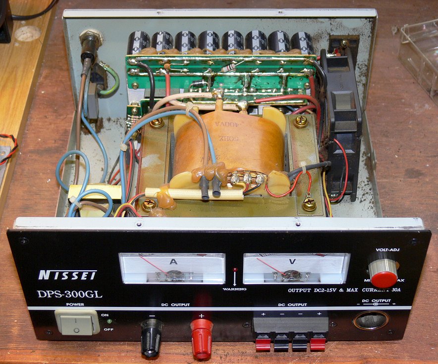
The power supply is called a "Nissei DPS-300GL" and is quite a hefty beast. Opening it up I found it to be quite nicely constructed, albeit rather grubby as the cooling fan had been dragging unfiltered air in and across the internal heatsink for many an hour. However, no matter what the outcome of my efforts was, the fan would drag no more air as it was completely seized up beyond redemption.


Inside the Nissei PSU (quite neat isn't it?)


My earlier deliberations had led me to suspect a problem with the overvoltage circuit, but I adopted a technique I have used on many occasions to prove or otherwise the general health of power supplies, and that was to connect a current limited supply at the correct DC voltage across the main rectifier output. Encouragingly this brought the majority of the power supply to life, at the same time lending weight to my original theory about the overvoltage tripping circuit which was fed from a completely separate supply via its own transformer.

Next I moved the external supply to the rectifier in the overvoltage circuit, and to my slight surprise the "enabling" relay (the overvoltage trip drops out the relay which removes the AC mains supply to the main power supply transformer) was heard to operate. My original theory was that there was a fault with this relay, or its associated driving circuitry.

Fortunately this piece of circuitry is built on its own separate board and was relatively easy to extract and examine.

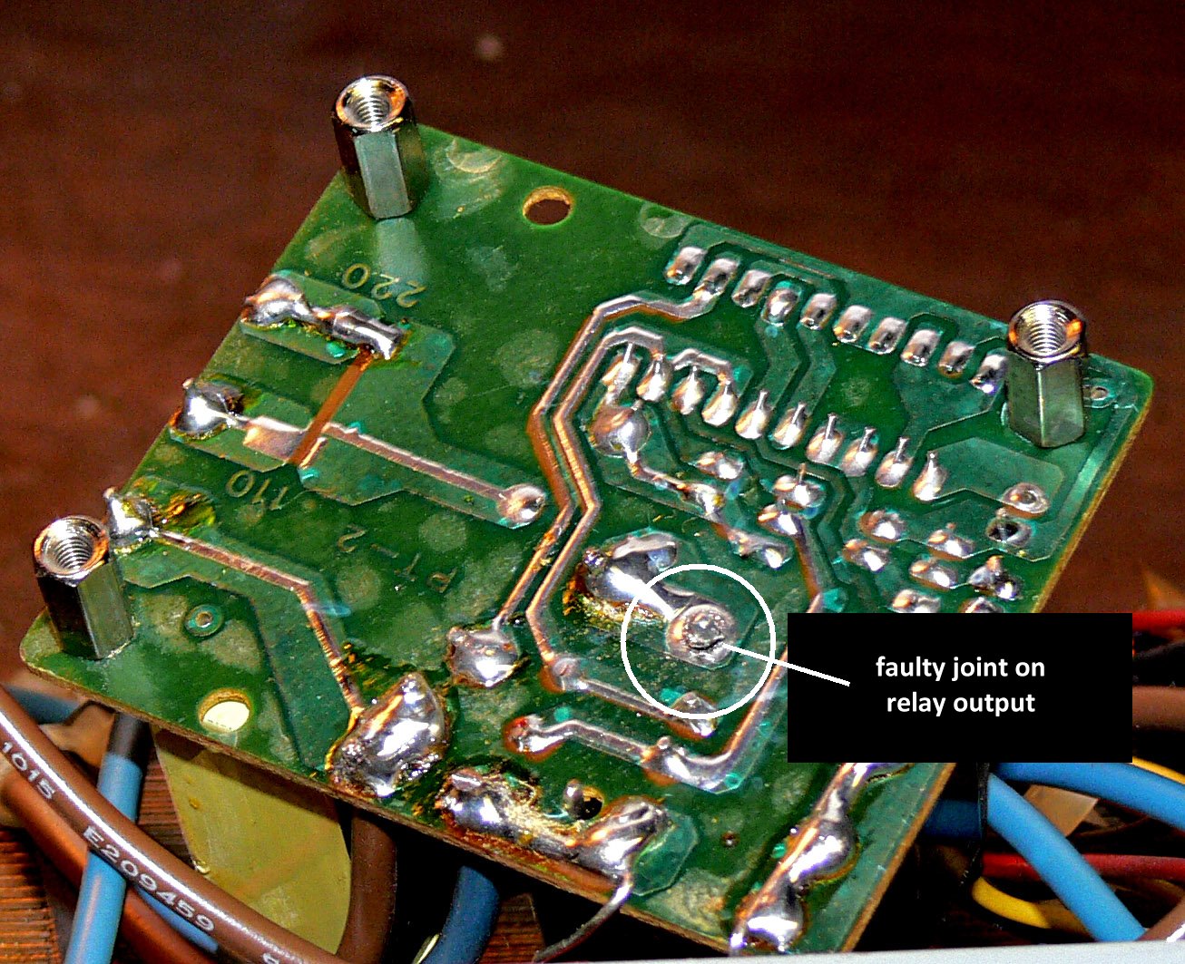
It didn't take long with an eye-glass and a multimeter to get to the root cause of the problem - see the attached photograph.
Underneath the Overvoltage Board ...

A nasty looking joint at the relay contact which switches the AC mains to the main part of the power supply. Bingo!

The joint was cleaned up and resoldered, the overvoltage circuit returned to its rightful place, the PSU powered up from its own mains supply, and lo and behold the PSU is now working, albeit temporarily without a cooling fan.   I realised at this point that the description of the original fault symptoms must have been slightly wrong in that the trip relay would have been heard to operate upon the application of mains, and I didn't verify this myself. Having said that this might have made me more worried about what the cause of the fault was!

Having spent a few frustrating minutes wrestling with Maplin's web site looking for a replacement,  EBay was consulted, and a 92mm 12V DC fan was quickly found and has been ordered for the princely sum of £4.99 (including postage!).

Soon Jim will have a spare power supply.

Right!  On with the next job ...

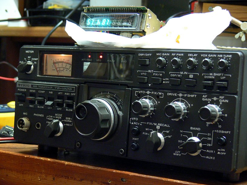
Today is the day I finally decided to start building my "X-lock", a VFO stabiliser kit from local firm Cumbria Designs.   I've had this "in stash" for quite a while as other projects have got in the way.  Once built I have then to decide which rig of my various"old ladies" will get the benefit.  At the time of writing I think it will be my FT-107, but that is by no means certain.   I also have it in the back of my mind to build the version described by Eamon Skelton EI9GQ which seems to be a variation upon the same theme.   Still, that will be a way off as I still have to "cut my teeth" properly with PIC programming, another medium-term objective of mine.  It will be interesting comparing the performance of the two units, and the advantage of the EI9GQ version is that the PIC source code is in the public domain, and I would have the opportunity to experiment with it.
X-Lock construction under way

Anyhow construction of the X-lock has now commenced, hopefully it can be finished off tomorrow, with luck.

Friday 18 February 2011

Deep Joy! A New (to me) source of meteor pings!

Tonight, courtesty of a link I found on Andy Smith's excellent TVCOMM web site, a really good list of current Band I (and other) frequencies in use, one of which is used by the Czech Republic. The transmitter is located near Ostrava, and runs at 100kW ERP.

I reckoned this to be a good distance for meteor reflections, so I tuned in my receiver and listened for a while, and, yes, I thought I heard the sound of meteor activity.

On came the software to track it down (first Spectrum Laboratory for a wide sweep, and then R_Meteor for a narrower sweep centred on a 1kHz beat note), and, yes, the unmistakable traces of meteors.


Now for the bad news - according to the link I referred to, this transmitter closes this November. But until then, I well keep looking!

The frequency I am monitoring, in case you are interested is 49.75949MHz, on my FT-920 which does not have any kind of precision frequency standard, just usual bog-standard crystal reference for the synthesiser. (Don't forget, this is offset from the "true" frequency by 1kHz so that the audio spectrum analyser based software works properly)

As you can see from the image above, I am getting LOTS of pings.

Wednesday 26 January 2011

Radio Prague - Another R.I.P., I'm Afraid ...

I don't really want to appear to be a "doom and gloom merchant", but a chance series of events caused me to learn that we (shortwave listeners) are about to lose another source of programming on shortwave, that of the very well known and respected "Radio Prague".

The sequence of events to which I refer started with the fitting of a 6kHz AM filter to one of my "classic" old transceivers, my FT-107M.

The filter was acquired from a fellow amateur who had acquired an FT-101ZD complete with said filter, but who wanted to return it to its "factory condition". For those not in the know, the FT-101ZD though equipped with AM facilities (a special board had to be acquired) had a rather lame implementation of this mode due to the way the "IF Shift" was connected (long story). The bottom line of this tale was that this particular FT-101ZD owner and myself eventually figured out what the previous owner had done and the modification was successfully undone, and the grateful new owner awarded me the unwanted AM filter as my reward!

This was a mutually acceptable arrangement, and today was the day I decided I would fit this filter to my FT-107M, as that particular radio implements the AM mode "properly".

The fitting of the filter to this radio was simplicity itself, and when it was done I decided to have a little tune around the 7MHz, or "41 metre" band looking for broadcast signals.

In early morning there is no shortage of strong signals from Europe, and before long I found myself listening to Radio Prague on 7.345MHz for the umpteenth time in my life.

As is usual these days shortly before the radio station closed down its English broadcast the announcer gave out some information about how to find Radio Prague on the Web (www.radio.cz), and a few minutes later I surfed into that very web site, like one does.

To my dismay my eyes alighted straight away onto a piece entitled "Radio Prague's shortwave broadcasting to end on January 31, 2011", the content of the article citing budget cuts as the reason why.

Now, the economics of shortwave broadcasting are a subject not unknown to me, as earlier in my life I worked in this medium, and was familiar enough with costs due to the fact that I actually signed cheques payable to the Regional Electricity Company who supplied the power to a major shortwave broadcasting station! Been there, done that, got the T-shirt ...

What I could never really relate to was the "value" in such broadcasting, as, being a Brit, I only ever was a "hobby" consumer of this medium. I was always told that overseas things were very different, and the average man-in-the street relied on shortwave to bring him news just as much, if not more so as he relied on his daily newspaper. I am sure this has been very true, but I wonder whether it is still true. I strongly suspect that it isn't, generally speaking, and, logically, many other broadcasting stations will soon be going the way of Radio Prague.

I would say, therefore, "enjoy them while you can" !

Friday 21 January 2011

G8LBT flies again, or is it nostalgia taken a step too far?

Those who have seen my QRZ.com entry will know that I have been planning to resurrect my old G8 call. This has now happened, the paperwork arriving today. So I am now the proud owner of TWO UK callsigns!

It's a wee bit curious why as to why this is permitted, and though I tell myself I am not one to covet another man's possessions, when I learned some while ago that some of my radio friends were in possession of both their old class B callsign and their more recent one, I felt I had to join this particular club.

I have had one or two arguments with folk who say they were told upon upgrading their licence when they achieved the Holy Grail of the 12 wpm morse test, or whatever, that they could NOT keep their old callsign.

However, the current regulations allow for (and this is quite clear from the text of the current Amateur Licence Application Form OF346) that a LAPSED licence (Class "A" or Class "B") previously issued to the applicant can be reissued upon production of certain documentary evidence that the applicant did at one time hold that callsign.

This latter condition wasn't too difficult for one such as myself who hardly ever throws anything away, and faded correspondence between myself and the then regulatory body (Home Office) was scanned and reprinted, catalogued with a covering explanatory letter and compiled into a dossier complete with OF346 filled in, and hey presto, two weeks later G8LBT was reborn!

I'm still not quite sure why I did it! Maybe it rolls off the morse key a little more nicely than my G4 one?

Saturday 8 January 2011

eQSL- why are so many hams so "sniffy" about it?

Apropos of nothing, today I received one of the occasional EMails I get say that there was an "eQSL" awaiting me at www.eqsl.cc.

When I logged in I was greeted with the news that my membership had been "downgraded" (in other words I hadn't made a financial contribution for over a year), so I duly fired up the PayPal screen and bunged them a few quid, as I have always thought that this service has been worth supporting. No big deal.

However this prompted a mental process which recalled all the "please no eqsl" messages I had seen scrolling across the screen whilst operating PSK modes, and I thought to myself "Why the heck not?".

It's completely understandable view from someone who has no PC or internet connection, but my experience is that the vast majority of hams across the world are now connected to the 'net, and therefore by definition (almost) must have a PC available to assist them in their hobby. Certainly virtually every PSK operator has a PC, as that is how that mode usually operates!

I realise that there are "issues" with eQSL not being "acceptable for awards", probably due to "authenticity" issues, (from the point of view of one who _doesn't_ chase awards), but on the whole I find it a splendid service; easy to use, inexpensive (you can use the system completely FREE OF CHARGE if you wish, albeit with some limitations in functionality, which I think is a pretty fair deal), and reliable (I can't recall any service outages over the period I have been using it).

The "accepted" alternative is the ARRL's LotW (Logbook of the World), which, apparently addresses the "authenticity" issues, but which is an absolute pain-in-the-arse to use (IMHO), and doesn't produce any kind of "QSL card" which eQSL does. When my LotW account needed revalidating recently, I had a heck of a job remembering and working out just how I was supposed do do it, and although I got there in the end, I was almost on the point of giving up before I hit on the correct combination of actions.

Some hams like to plaster their shack walls, or fill shoeboxes with pieces of cardboard commemorating contacts - I'm not included in this list, being perfectly happy to have a line in a logbook, or an electronic record such as eQSL.cc provides, and I accept that it "takes all sorts", but "PSE NO EQSL" does seem to be a "dog in a manger" attitude to me!

One QRZ.com entry I came across the other day stated that paper QSL cards were "honourable", and implying therefore the eQSLs were not. I think you can tell that I do not share this opinion.