Showing posts with label CMOS. Show all posts

Sunday, 27 November 2011

TS-180S - this is getting ridiculous!

I knew it was a mistake putting the lid on properly.
Having restored the functionality of the frequency display I decided to run the radio for a few hours over the weekend to evaluate performance further.   Still no tx, of course or any PLL locking on 28MHz but I knew that already ...
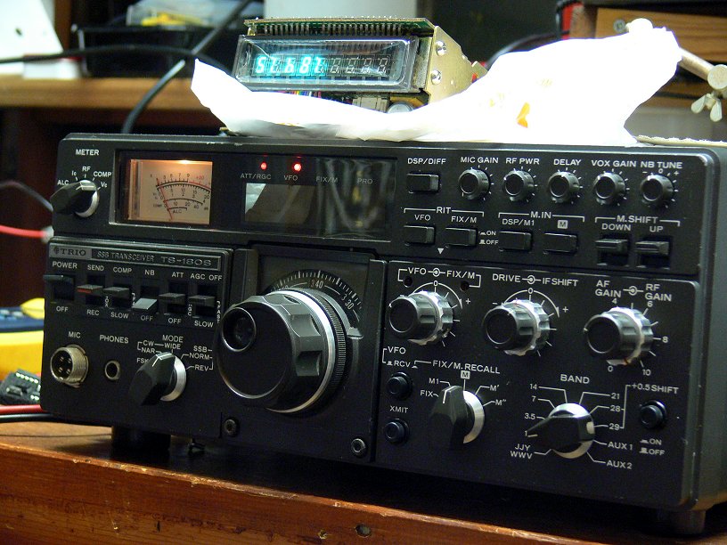
I was listening to a QSO on 7MHz this morning between a very strong Belgian station and a string of UK stations, most of whom I could hear reasonably well when I realised that the frequency seemed to be locked on to 7.150.0MHz.  Tuning either side by a kHz or two made no difference to the display.   I had a funny feeling about this, so I tuned up and down the band to find that lo and behold that the display was only displaying frequency to a 10kHz resolution!
To see whether this was a heat related issue I switched the radio off and let it cool down for half an hour or so, but on re-powering the fault was still present, so I have concluded that I have ANOTHER dead chip!  More than likely a duff 7490 in the counter chain, and that's TTL not CMOS, so another theory goes down the pan.
It is now only sheer stubbornness which is sustaining my interest in this project.  In all the years of building and repairing equipment, I don't think I've ever come across a project like this.   Trying to fix up a radio with numerous faults is one thing (and what I thought I was dealing with here), but fixing one which keeps breaking seemingly randomly whilst under repair is quite something else.   It's a case of either "nolum illigitimus carborundum", or chuck the bloody thing in the (recycling) bin!  I don't give up easily though.  What kind of trauma has this radio suffered in the past?   It's anybody's guess.

Saturday, 26 November 2011

TS-180S Display Fixed (Again!)

As I reported previously I discovered that the display in my TS-180S which is currently undergoing major restoration was again faulty.

The symptoms were either that it displayed just the "base" frequency of the band in use when it was powered up, "1.500.0" for example on Top Band, "3.500.0" on 80m, or another sequence of numbers unrelated to anything.  None of these numbers changed when the bandswitch was operated with the set switched on.

A couple of nights ago I decided to have a look with my test gear to find out what was going on, or not.

The trickiest part of the whole operation is extracting the display from the radio, and conversely refitting it after investigation, and this struggle led me to suppose before I started that the fault was induced during the arduous refitting after the previous repair, and the consequential tidying up of the cable harness.

This was soon proved not to be the case as investigation with an oscilloscope quickly led me to the conclusion that (a) there was plenty of 40-40.5 MHz signal from the premix unit but (b) there was no gate signal in the digital counting chain.

So attention returned to the previously repaired divide unit which sits underneath the main counter board, and so consequently the whole caboodle had to be extracted once again from the radio so I could get at it.

Well at least I was well practiced at this, and knew what to do (familiarity doesn't imply enjoyment!), so eventually, after cutting some of my nicely installed cable ties, and much cussing, I had the recalcitrant unit upended so I could investigate.

TS-180S Display Divide Unit
The marked up drawing above shows what I found, and I quickly came to the conclusion that either Q8 or Q9 would appear to be faulty, with the balance of probabilities suggesting Q8.
 
Fortunately a trawl through my spare parts revealed that I had a 4013 (Dual D-Type Flip-Flop) and also a 7400 if required, so I had a "cunning plan" to replace these parts in the radio the following evening.


Divider Board - Q8 Bottom Right
 
And so it came to pass.  The following evening Q8 came out as sweet as a nut (it was helpful that it was in the corner of the board and no immediately surrounding components, a new 14-pin turned pin socket was soldered in and the new chip installed.
 
Powering up the radio followed and to my great delight the correct frequency display appeared!  Yay!
 
Display Correct (note - upside down!)

Display ready to go back in ...

The display has now been refitted and is working as I type this, so after much effort, I am now back where I started and wondering (a) what on earth will go wrong next? and (b) how can one radio have had so many seemingly unrelated faults?    The only connection I can think of between this fault and the previous repair to the divide unit is that both of the faulty chips were CMOS types of presumably similar vintage?  Maybe the anti-static handling precautions at the factory weren't up to much at the time?
 

Faulty Q8 - Innocent Looking, eh?


Friday, 24 June 2011

TS-180S Repair - Part 4 - That's More Like It!

Great progress to report, and more dead bits!

The frequency counter unit is now working properly.

The two DC-coupled "front end" transistors in the 40MHz amplifier section were suspected as being faulty and were replaced. No exact replacements or direct equivalents were to hand, but looking at the specifications of the original units (2SC460) I figured that more or less any old small signal RF transistor would do, and as I had a bag full of MPSH-10s in my spares box I used those. The pinouts are incompatible and I ended up mounting them under the board.

Anyhow to my great delight the frequency counter then appeared to work, albeit not quite properly. The frequency count was correct at the bottom band edge (e.g. 7.000MHz) but when I tuned a signal at 7.100MHz the counter read 7.060MHz, near as makes no difference. This was consistent across all bands. The counter was proportionally out of kilter receiving at 7.200MHz, the counter reading 7.120MHz

Owing to the frequency scheme in use in this transceiver, and the fact that basically the counter is fed with frequency of 40.0 to 40.5MHz as the VFO is tuned across each band I figured there was a counter timebase problem.   The microprocessor logic in the counter unit adds the base frequency for each band to the difference between the 40.0 to 40.5MHz and 40MHz producing the correct frequency on the display.
Underside view of Counter Unit
Investigation of the divider part of the circuit revealed a problem with Q5, a CMOS BCD counter (4018) which was producing an output of 83Hz instead of the required 50Hz. Ha! That explained everything!  The frequency being too high would mean a shorter gate time for the counter than is required, and hence the frequency count would be too low.  This signal goes through a further division-by-10 process (a 7490 TTL chip) before the 5Hz, or in the case of this faulty radio 8.3Hz gating signal is sent to the counter signal chain.

Oscilloscope display of output from faulty Q5
The repetition rate of the waveform should be 20ms not 12ms!

Below:- the replaced Q5 - the replacement has obviously been in my spares box for quite a while!


This faulty chip has now been replaced, and the counter is now functioning correctly, and I'm feeling very happy with the way this repair is shaping up.


Here is the old girl on the "operating table" ..

I'm just about ready to see if the set transmits ...
Latest update - no it does't,  so it's on to the next fault (again!) ...