Showing posts with label amateur radio. Show all posts

Friday, 3 May 2013

High Altitude Ballooning

For a little while now I’ve been fascinated by the hobby of “High Altitude Ballooning“.
It’s such a short while that I can’t yet claim to be an expert in that subject, but what I have seen has really sparked my interest and imagination.

I stumbled on a page on the  "Raspberry Pi" web site, and it turned out that the "Pi" and ballooning have been bedfellows for quite a while.    Furthermore it seems that the BBC's James May (Man Lab) and Channel 5's Gadget Show  have have featured balloons, but as someone who rarely watches TV (even more rarely now Time Team has been axed!), this has only recently come to my attention.

This particular activity, and the background to it appears to pull together a number of disciplines, and it’s the amalgamation of these which has really got me excited.

Once I discovered, almost by chance that the telemetry transmitter from HABs (High Altitude Balloons) could be received at my modest radio station from a distance of 200+ miles I realised I could participate in this activity, even if I never actually went near a balloon.

Even more exciting was the realisation that many of the participants in this activity sre relatively young people.    I've long felt that it is high time that the younger element of our population took up the baton of technical innovation and put those of us of the “older generation” firmly in our place.

It’s not exclusively the dominion of the young, but there appear to be proportionally more of the younger generation taking part than say in “vanilla” Amateur Radio.

Great!

Here are a few web links to enlighten you further, if you are interested :-

UK High Altitude Societywww.ukhas.org.uk

SpaceNear Online Tracker (Google Maps based application) -  spacenear.us/tracker
Note that ballooning is popular on the Continent as well as in the UK, especially in Poland.

StratoDean – a fabulous blog maintained by participants from the Forest of Deanwww.stratodean.co.uk

Balloon flights tend to take place at weekends when the weather is favourable.  “Weather” doesn’t just mean what the weather is like at ground level, but also what the winds are doing in the stratosphere as these balloons usually achieve an altitude of over 30,000 metres (yes, 30km!), and the participants aren’t too keen on flight predictions which end in either the sea or in foreign countries!


 The above graph lifted from the spacenear.us online tracking application shows the flight profile of a recent flight and clearly shows what is likely to be achieved in terms of altitude and duration.

A flight in the south of England becomes audible to my station in the north of England once it gets to around 10km in altitude, and the telemetry  transmissions are generally decodable throughout this phase of the flight.

Telemetry is transmitted from the payload using small proprietary low power transmitters which happen to use part of the amateur "70cm" band, which is basically where we radio amateurs come in - many of us have high specification equipment and aerials capable of receiving these transmissions.   In my case I use my trusty Diamond dual band (2m/70cm) co-linear and my FunCubeDongle ProPlus SDR, see below.


The above picture is a composite (ie more than one image has been stitched together to make a single image) screen grab of  a “Spectrum Laboratory” screen and shows in graphical form the strength of the signal from the “Stratodean1″ flight from around 0945 UTC until about 11:30 UTC when the signal was finally lost as the payload descended under its parachute.  NOTE: The sudden “steps” in the display were caused by me adjusting my receiver to get the signal “centered” in the passband of the display, and were not caused by a problem with the payload telemetry transmitter!

Just to give you an idea of how remarkable radio transmission are above 10km, note that the transmitter power is 10mW, and the aerial on the payload is a simple ground plane affair made by using a length of stripped back coaxial cable and drinking straws!   See the StratoDean web site for more information about this and other technical details about the payload.

The screen grab below shows the flight profile for StratodeanOne and I've marked it up to highlight the part of the flight I was able to receive in Penrith (IO84 square).


Saturday, 29 October 2011

Virus (or Trojan?) Attack

I have to report that my main "Radio PC" is down having contracted something nasty yesterday.

Basically it all started when I discovered that the DVD/RW on my main PC seemed to be duff, and so I tried to burn a DVD on my Radio PC which is a Dell Dimension 3100 running Windows XP Home Edition.

That was a failure, as it appeared that the DVD/RW in the Dell was also u/s, and after doing some research on the web, I tried to download a new driver for it.

It seems that "driver sites" are now as bad as "keygen" sites used to be at harbouring nasty things, and to cut a long story short I very soon had a crippled PC, and still have.

First it was a BSOD (Blue Screen of Death) with a number of "Stop Codes" which I was unable to find a satisfactory explanation for.

I then "repaired" the Windows installation from the OEM CD which got it going again, but as soon as I had it fired up I noticed that Microsoft Security Essentials appeared to have been "nobbled" in that the real time scanning couldn't be enabled, and examination with TCPView revealed dozens of TCP connections opening up, at which point I quickly removed the network connection from the PC.

As of now I haven't been able to find the root cause - a deep scan with Security Essentials, followed by SpyBot Search and Destroy revealed nothing, but there is definitely something nasty in there, and it will have to be complete purge, reformat and reinstall from scratch, I'm afraid.

Web sites being hosted on that PC have been found alternative accommodation, and I now need to think about what I must rescue in the way of data (My HRD logbook is in there for one thing) before I "slash and burn" and start again.

Doesn't it make you sick!

Yours, grumpily

Saturday, 16 July 2011

TS-180S : Part 6 - Life Moves On ... (things looking Black!)

Since my last post more hours have been expended on this old radio.  To summarise :-
Numerous hours spent with the TS-180S connected to an aerial simply being a receiver.   The purpose of this was fourfold ;
1) Get some hours on the clock to see if any further "corrosion related faults" arose (they didn't)
2) To evaluate the intrinsic frequency stability of the transceiver (it proved to be acceptable for the technology of the day)
3)To evaluate its performance as a receiver (it lacks sensitivity - a lack of IF stage gain is prime suspect)
4) Allow me to ponder how to tackle the lack of transmit output (there is a very small amount of RF transmitted, but I think I need to tackle the suspected IF gain issue first as part of the IF is used in the transmit chain)
Anyhow with all this input to my overloaded brain I resolved that the time had come to put this project on the back burner therefore allowing me to move other projects on as I perceived I was becoming somewhat obsessed with this one!
Having made that decision I decided I would reunite the radio with its covers, albeit temporarily, and that is when I noticed something I had missed.  There on the bottom half of the case, on the inside was pretty conclusive evidence of some kind of "spill" which had pooled in the bottom of the case leaving a residue!
Ha!  I think my earlier suspicions have been proved correct.  Judging from the size of the marks inside the lid, it was clearly a sizable spill.
When I return to this project it will be armed with that knowledge, and I will need to bear in mind what other damage may have been done, and seriously consider what the chances are of a full restoration without a ridiculous amount of expense.

Saturday, 2 July 2011

TS-180S - Part 5 - Swimming Against the Tide

Well it sure feels like it!

Having restored receive functionality to this old set, and having then established that the transmit function was u/s, I set about figuring out a strategy to find out what the problem, or more likely problems were which prevented me from transmitting.

You always need a strategy of some sort, and I wanted to come up with one.   The most obvious thing I noticed at this point was that the ALC reading on the metering was "pinned" when I put the set to transmit.

This could be cause, or a symptom.  Anyway, some place to start, a little piece of evidence to build on.

Whilst all this was going on in my head, the radio was powered up and receiving lots of signals.  I began to notice an unusual tone to the received signals, and upon investigating this I realised that the frequency had developed a nasty "wobble", jumping about by small amounts.  I also noticed that the radio was pulling around 100mA more current from my  power supply than it used to, so something was clearly wrong.

I established fairly quickly that the 8V regulated rail from the AVR unit had increased to nearly 9V and was fluctuating.  It was possible to trim this back to 8V but the fluctuations continued.  This is when I noticed Q6 on this board running VERY hot.

Further investigation of voltages around the circuit established that the Q6/Q7 pair (the shunt voltage regulator error amplifier) was "up the creek" (Remember Q5 in this circuit was one of the first faults I found on this set).

Q6 was found to be short circuit from collector to base, and when Q7 was removed, I found ANOTHER case of "rotten transistor leg syndrome".

I am very suspicious now that at some point in the past this transceiver had some unpleasant, corrosive liquid spilt into it, or something of that nature way back in it's past.   That might explain a thing or two ...
Dead Q6 at the top (base lead looks "iffy too!) Q7 with collector lead (middle) almost eaten through.  The 180 ohm resistor R11 is absolutely fine.

Replacing both of these transistors has restored everything to normal - 2N3704s used to replace the 2SC945s - the base and collector terminals just need to be transposed.

Right, where were we? . . .

Friday, 24 June 2011

TS-180S Repair - Part 4 - That's More Like It!

Great progress to report, and more dead bits!

The frequency counter unit is now working properly.

The two DC-coupled "front end" transistors in the 40MHz amplifier section were suspected as being faulty and were replaced. No exact replacements or direct equivalents were to hand, but looking at the specifications of the original units (2SC460) I figured that more or less any old small signal RF transistor would do, and as I had a bag full of MPSH-10s in my spares box I used those. The pinouts are incompatible and I ended up mounting them under the board.

Anyhow to my great delight the frequency counter then appeared to work, albeit not quite properly. The frequency count was correct at the bottom band edge (e.g. 7.000MHz) but when I tuned a signal at 7.100MHz the counter read 7.060MHz, near as makes no difference. This was consistent across all bands. The counter was proportionally out of kilter receiving at 7.200MHz, the counter reading 7.120MHz

Owing to the frequency scheme in use in this transceiver, and the fact that basically the counter is fed with frequency of 40.0 to 40.5MHz as the VFO is tuned across each band I figured there was a counter timebase problem.   The microprocessor logic in the counter unit adds the base frequency for each band to the difference between the 40.0 to 40.5MHz and 40MHz producing the correct frequency on the display.
Underside view of Counter Unit
Investigation of the divider part of the circuit revealed a problem with Q5, a CMOS BCD counter (4018) which was producing an output of 83Hz instead of the required 50Hz. Ha! That explained everything!  The frequency being too high would mean a shorter gate time for the counter than is required, and hence the frequency count would be too low.  This signal goes through a further division-by-10 process (a 7490 TTL chip) before the 5Hz, or in the case of this faulty radio 8.3Hz gating signal is sent to the counter signal chain.

Oscilloscope display of output from faulty Q5
The repetition rate of the waveform should be 20ms not 12ms!

Below:- the replaced Q5 - the replacement has obviously been in my spares box for quite a while!


This faulty chip has now been replaced, and the counter is now functioning correctly, and I'm feeling very happy with the way this repair is shaping up.


Here is the old girl on the "operating table" ..

I'm just about ready to see if the set transmits ...
Latest update - no it does't,  so it's on to the next fault (again!) ...

Monday, 13 June 2011

TS-180S Repair Part 3 : Recovery in progress, but the Body Count is Increasing ...

I am aware that it has been a while since my last update on this subject, but work has been progressing quietly in the background as my limited free time has allowed. At least once careful consideration was given to this old lady "becoming a projectile", or to be more serious whether a time was approaching when I would could my losses and put it to one side as it seemed to be taking over my life! However after a brief break I rolled up my sleeves and carried on ...

I am pleased to report that this transceiver now works as a receiver, albeit not on all bands yet, and the frequency display isn't functioning. The time is fast approaching when I will check out the transmitting capability and performance of this venerable transceiver.


The replacement of the dead 2SC1907 in the Q14 position (PLL WBA) allowed me to move on to the next fault (there always seems to be a "next fault" with this radio!) - it still appeared that the PLL circuitry was the problem area.

I revisited the Premix Unit, and although all the various signals appeared to be there I was not convinced that the RF levels were all that they should be.   The Service Manual is rather vague on expected RF levels, though it is very good at expected DC levels around key parts of the circuitry.

Meanwhile, back at the PLL Unit I discovered that the amplified VCO outputs which are fed to the Premix Unit were suspiciously low whereas the VCO output levels themselves seemed to be reasonable.

TS-180S - PLL Circuit (Part)
Attention was therefore drawn to the output stage of this part of the circuit (see excerpt from the circuit), and probing around with my DVM revealed that Q2 (another 2SC1907) had just over a volt between its base and emitter and that Q3, the "unlock output mute" transistor had no volts on its collector.  The other voltages were not very close to those suggested by the Service Manual.

Small signal transistors with a volt showing across base and emitter simply aren't transistors any more (it's a kind of Law of Physics!) and clearly the load choke of the mute transistor was open circuit.

The transistor and choke were replaced, and the radio burst into life! Furthermore, replacing the components restored the DC voltages to being very close to those suggested by the Service Manual, an interesting lesson there for future use. (Note to self:- check the DC voltages first!)

It is interesting to ponder that both of the u/s transistors found so far in this circuit were identical types.  This possibly suggest a quality issue with the manufacturing as I strongly suspect they would have been made at the same time, more than likely from the same piece of material.   Worryingly there are a few more 2SC1907s in this radio!

 Now I have a radio which appears to work as a receiver on most but not all bands - there appear to be some alignment issues still with the PLL, but the frequency display now just shows the "base" frequency for each band, in short the counter isn't working.

I spent a little bit of time investigating the counter issue, and again I am not convinced the signal levels are quite sufficient.  The counted signal is a 40-40.5 MHz VFO-locked signal from the Premix Unit and has to be amplified to a sufficient level to interface with TTL (yes, TTL!) chips, and I don't think this is quite happening, but when I lifted the circuit board to investigate the underside I had a bit of a shock!

TS-180S - counter underside

The components underneath were a surprise, and suggest that the layout of this board isn't what you would call "Kenwood's Finest Moment"!.  However to be fair the added bits are shown in the Service Manual layouts, if you look carefully, and are, in the main added decoupling components to the TTL chip supply pins, or the tying down of unused pins.

Re-sweating some suspicious-looking joints and plated-through holes didn't appear to make any difference, but it's early days yet ...

Sunday, 1 May 2011

First Es (Sporadic-E) Opening of the Season

My radio friends know that I spend a lot of energy (mental and electrical) monitoring distant Band I TV stations looking for and recording the effects of meteors on the propagation of signals between that remote transmitter and myself.

A side effect of this is that when Sporadic-E (Es) propagation occurs at the critical point along that path, the effect is obvious.

I was only commenting to two local friends two days ago that this year's Sporadic-E season seems to be late in starting, and my friends were in agreement with that statement.

This morning's events though took an interesting turn at 0906 GMT when the path from Ostrava in the Czech Republic was suddenly enhanced by a burst of Es which lasted for around ten minutes.

The frequency used by the Ostrava TV transmitter is 49.76MHz, just below the amateur "six metre" allocation.


(above) R_Meteor Trace of first Es Opening

SpectrumLab Trace of Es Opening (note +/- 25Hz Sidebands)

By a bizarre coincidence, as I type this entry, I have just heard a Spanish station EA3FER calling CQ in CW on 50.092MHz and shortly after another Spanish station, this time an EA6 call from the Balearics, so it appears that the 6-metre Es season has finally started!

Saturday, 19 March 2011

Bringing the TS-180 Back from the Dead - Part 1: The Darndest Fault!

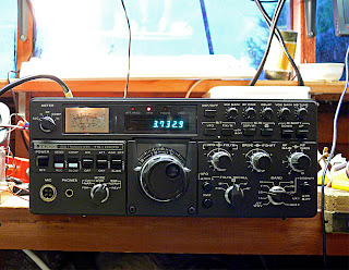
Some little time ago I purchased a "Spares or Repair" Trio-badged TS-180S from an eBay Trader, the price I paid reflected its non-working condition.    I didn't know very much at all about the TS-180S at the time but fancied a challenge.

As I've put my Eden9 70MHz transceiver on the "back burner" for a while and cleared one or two other repair jobs, I finally decided that the time was right to make a start on the '180S.

A preliminary look under the lid on the day the radio arrived revealed that the radio was totally u/s.  The famous Trio/Kenwood "dots" on the display on all bands, and a quick poke around with a DVM revealed that the regulated outputs from the "AVR" board were all over the place.  The whole thing smacked of multiple problems so I was anticipating a bit of a struggle.  The radio may yet prove to be Beyond Economic Repair, only time can tell if that is going to be the case.

Forearmed with this knowledge I decided to have a look at the AVR board for starters.

This consists of three regulator circuits.   One is a DC-DC converter which produces a light duty negative rail.   This appears to be working fine.

The other two parts are shunt regulators (oh dear, I dislike shunt regulators!) producing 8 volts (adjustable)  and 8.1V (non-adjustable) respectively.   These were producing 5 and a bit volts which didn't respond to adjusting and 8.9 volts respectively but are independent of one another save for the fact that the unregulated input rail is common to both.

As it seemed to be the most out of kilter I decided to look at the 8V adjustable supply first.

Having scribbled the circuit out on a pad and made some voltage measurements and jotted them down I homed in on what I felt would be a likely candidate for being faulty.   Shunt regulators are pretty horrible circuits in my view, not so much due to their complexity (they aren't usually all that complex) but due to the way the various stages (voltage reference, error amplifier, regulator driver and regulator) are wrapped up in a tight loop and DC-coupled, fault finding on them can be tricky as a fault in one part of the circuit ripples right through the circuit cutting off or destroying transistors and causing Magic Smoke to be lost from the system.

I didn't appear to have any overstressed components in my circuit, but I certainly appeared to have transistors which were just acting like resistors so I took a punt on the regulator driver being a suspect worthy of investigation.   What I found amazed me.

I removed (or so I thought) some solder from the PCB pads under Q5 the suspect device and tugged on it from the top, and away it came fairly easily.     However I noticed that the transistor legs seemed to be somewhat corroded, surprisingly, and I cleaned them off a bit with my pliers and tested the transistor on my DVM.  It looked absolutely fine.

Well I wasn't 100% convinced that Q5 was the culprit, and with it removed from the circuit, it would make the results of some other resistance tests on the remainder of the circuit easier to interpret, so I wasn't too discouraged.   However, when my attention returned to the board I noticed that I had actually de-soldered the wrong components, probably due to my not having been able to find my near-distance glasses!    The corroded remains of the transistor legs were still firmly attached to the PCB.

I managed to find a similar transistor to the original Japanese one in my junk box and eventually after some mental gymnastics with the different pinout replaced the original unit and re-soldered the remaining components.

The 8V regulator now works and is adjustable, so the original transistor must have had such badly corroded legs that it must have just basically appeared as a resistor network to the circuit.   I've never come across anything quite like that before in my fault-repairing experience.

Even better news, with the 8V supply restored, the radio is now showing some signs of life.   The PLL appears to lock on some bands (10,14 and 21MHz, though not across the whole band.

Nothing is being received even with the PLL locked, but it is a start!

I still have to figure out where the corrosion which ate the legs of the transistor came from - perhaps something liquid was dropped through the grille of the external case (this board is directly under the vent grille as it generates a reasonable amount of heat)?