Friday, 24 June 2011

TS-180S Repair - Part 4 - That's More Like It!

Great progress to report, and more dead bits!

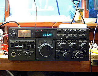
The frequency counter unit is now working properly.

The two DC-coupled "front end" transistors in the 40MHz amplifier section were suspected as being faulty and were replaced. No exact replacements or direct equivalents were to hand, but looking at the specifications of the original units (2SC460) I figured that more or less any old small signal RF transistor would do, and as I had a bag full of MPSH-10s in my spares box I used those. The pinouts are incompatible and I ended up mounting them under the board.

Anyhow to my great delight the frequency counter then appeared to work, albeit not quite properly. The frequency count was correct at the bottom band edge (e.g. 7.000MHz) but when I tuned a signal at 7.100MHz the counter read 7.060MHz, near as makes no difference. This was consistent across all bands. The counter was proportionally out of kilter receiving at 7.200MHz, the counter reading 7.120MHz

Owing to the frequency scheme in use in this transceiver, and the fact that basically the counter is fed with frequency of 40.0 to 40.5MHz as the VFO is tuned across each band I figured there was a counter timebase problem.   The microprocessor logic in the counter unit adds the base frequency for each band to the difference between the 40.0 to 40.5MHz and 40MHz producing the correct frequency on the display.
Underside view of Counter Unit
Investigation of the divider part of the circuit revealed a problem with Q5, a CMOS BCD counter (4018) which was producing an output of 83Hz instead of the required 50Hz. Ha! That explained everything!  The frequency being too high would mean a shorter gate time for the counter than is required, and hence the frequency count would be too low.  This signal goes through a further division-by-10 process (a 7490 TTL chip) before the 5Hz, or in the case of this faulty radio 8.3Hz gating signal is sent to the counter signal chain.

Oscilloscope display of output from faulty Q5
The repetition rate of the waveform should be 20ms not 12ms!

Below:- the replaced Q5 - the replacement has obviously been in my spares box for quite a while!


This faulty chip has now been replaced, and the counter is now functioning correctly, and I'm feeling very happy with the way this repair is shaping up.


Here is the old girl on the "operating table" ..

I'm just about ready to see if the set transmits ...
Latest update - no it does't,  so it's on to the next fault (again!) ...

Monday, 13 June 2011

TS-180S Repair Part 3 : Recovery in progress, but the Body Count is Increasing ...

I am aware that it has been a while since my last update on this subject, but work has been progressing quietly in the background as my limited free time has allowed. At least once careful consideration was given to this old lady "becoming a projectile", or to be more serious whether a time was approaching when I would could my losses and put it to one side as it seemed to be taking over my life! However after a brief break I rolled up my sleeves and carried on ...

I am pleased to report that this transceiver now works as a receiver, albeit not on all bands yet, and the frequency display isn't functioning. The time is fast approaching when I will check out the transmitting capability and performance of this venerable transceiver.


The replacement of the dead 2SC1907 in the Q14 position (PLL WBA) allowed me to move on to the next fault (there always seems to be a "next fault" with this radio!) - it still appeared that the PLL circuitry was the problem area.

I revisited the Premix Unit, and although all the various signals appeared to be there I was not convinced that the RF levels were all that they should be.   The Service Manual is rather vague on expected RF levels, though it is very good at expected DC levels around key parts of the circuitry.

Meanwhile, back at the PLL Unit I discovered that the amplified VCO outputs which are fed to the Premix Unit were suspiciously low whereas the VCO output levels themselves seemed to be reasonable.

TS-180S - PLL Circuit (Part)
Attention was therefore drawn to the output stage of this part of the circuit (see excerpt from the circuit), and probing around with my DVM revealed that Q2 (another 2SC1907) had just over a volt between its base and emitter and that Q3, the "unlock output mute" transistor had no volts on its collector.  The other voltages were not very close to those suggested by the Service Manual.

Small signal transistors with a volt showing across base and emitter simply aren't transistors any more (it's a kind of Law of Physics!) and clearly the load choke of the mute transistor was open circuit.

The transistor and choke were replaced, and the radio burst into life! Furthermore, replacing the components restored the DC voltages to being very close to those suggested by the Service Manual, an interesting lesson there for future use. (Note to self:- check the DC voltages first!)

It is interesting to ponder that both of the u/s transistors found so far in this circuit were identical types.  This possibly suggest a quality issue with the manufacturing as I strongly suspect they would have been made at the same time, more than likely from the same piece of material.   Worryingly there are a few more 2SC1907s in this radio!

 Now I have a radio which appears to work as a receiver on most but not all bands - there appear to be some alignment issues still with the PLL, but the frequency display now just shows the "base" frequency for each band, in short the counter isn't working.

I spent a little bit of time investigating the counter issue, and again I am not convinced the signal levels are quite sufficient.  The counted signal is a 40-40.5 MHz VFO-locked signal from the Premix Unit and has to be amplified to a sufficient level to interface with TTL (yes, TTL!) chips, and I don't think this is quite happening, but when I lifted the circuit board to investigate the underside I had a bit of a shock!

TS-180S - counter underside

The components underneath were a surprise, and suggest that the layout of this board isn't what you would call "Kenwood's Finest Moment"!.  However to be fair the added bits are shown in the Service Manual layouts, if you look carefully, and are, in the main added decoupling components to the TTL chip supply pins, or the tying down of unused pins.

Re-sweating some suspicious-looking joints and plated-through holes didn't appear to make any difference, but it's early days yet ...